Display equipment, display method, and recording medium for recording display control program

a display control and display method technology, applied in the field of display equipment, can solve the problems of heavy system resources, such as the inability to display original images such as photographs downloaded from a server, and the inability to use such large system resources, and achieve the effects of less system load, reduced variation in output image density, and high-quality display

Active Publication Date: 2007-01-02
SOVEREIGN PEAK VENTURES LLC
View PDF59 Cites 51 Cited by
  • Summary
  • Abstract
  • Description
  • Claims
  • Application Information

AI Technical Summary

Benefits of technology

[0029]This structure allows a pixel to be displaced by amounts of some sub-pixels in the first direction according to respective values of “x” and “y” without any change in pixel value.
[0030]Such a construction provides a suppressed variation in output image density when an image is displayed on a per sub-pixel basis. Such a density variation otherwise would conspicuously occurs as a result of a variation in line width that represents an object. This feature realizes a high-quality display on a per sub-pixel basis.
[0031]The pattern-determining unit dynamically determines a three-times magnified pattern and sub-pixel patterns next thereto on the basis of a raster image. This means that the three-times magnified pattern and the sub-pixel patterns need not be retained statically. This feature provides less system loads than when the three-times magnified pattern and the sub-pixel patterns are statically contained. This beneficial effect in combination with the above-described beneficial effects allows the display equipment according to the present invention to be incorporated with more ease into equipment having many constraints on system resources.

Problems solved by technology

In particular, for equipment such as a cellular phone and a mobile computer, which have many constraints on system resources, the art that involves such large system resources is difficult to employ.
Therefore, any original image such as a photographic portrait image downloaded from a server cannot be displayed using a three-times magnified resolution.
As evidenced by the above, the prior art has a problem that heavy loads are imposed on the system resources although an image can be displayed on a per sub-pixel basis.
A further problem with the prior art is that the image on a per sub-pixel basis is provided only within limited applications.

Method used


Image

  • Display equipment, display method, and recording medium for recording display control program
  • Display equipment, display method, and recording medium for recording display control program
  • Display equipment, display method, and recording medium for recording display control program

Examples


embodiment 1

(Embodiment 1)

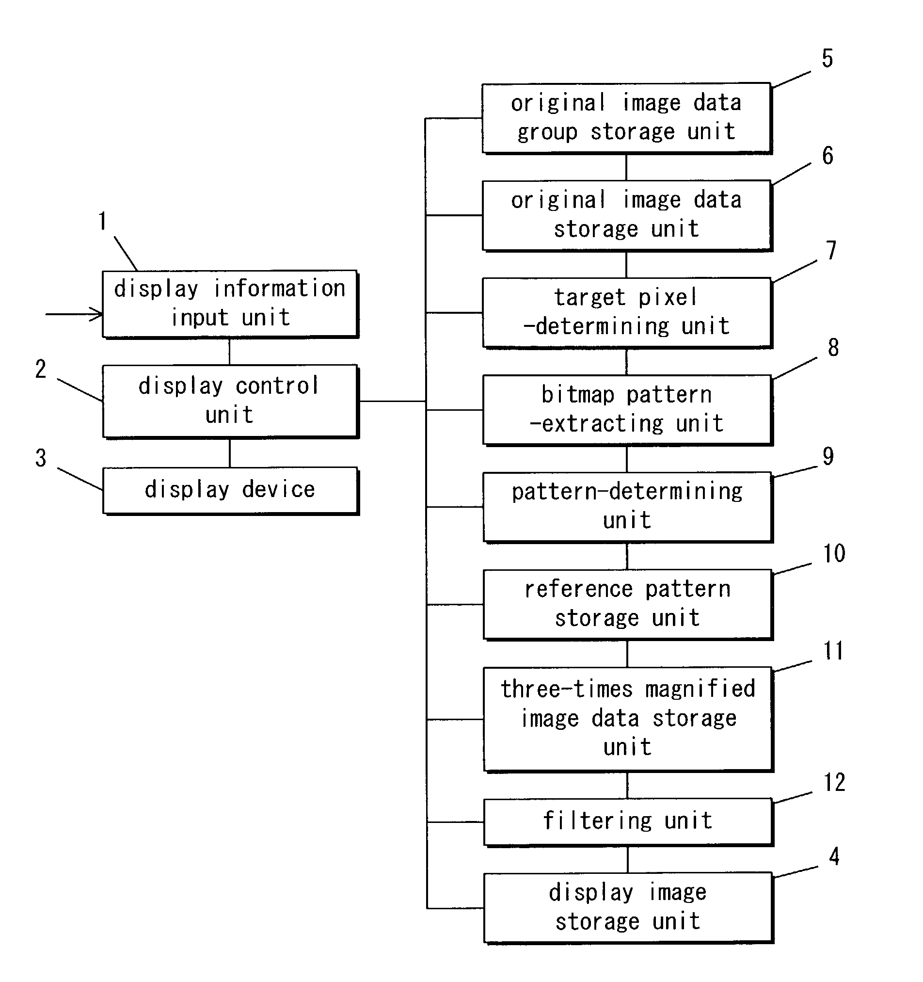
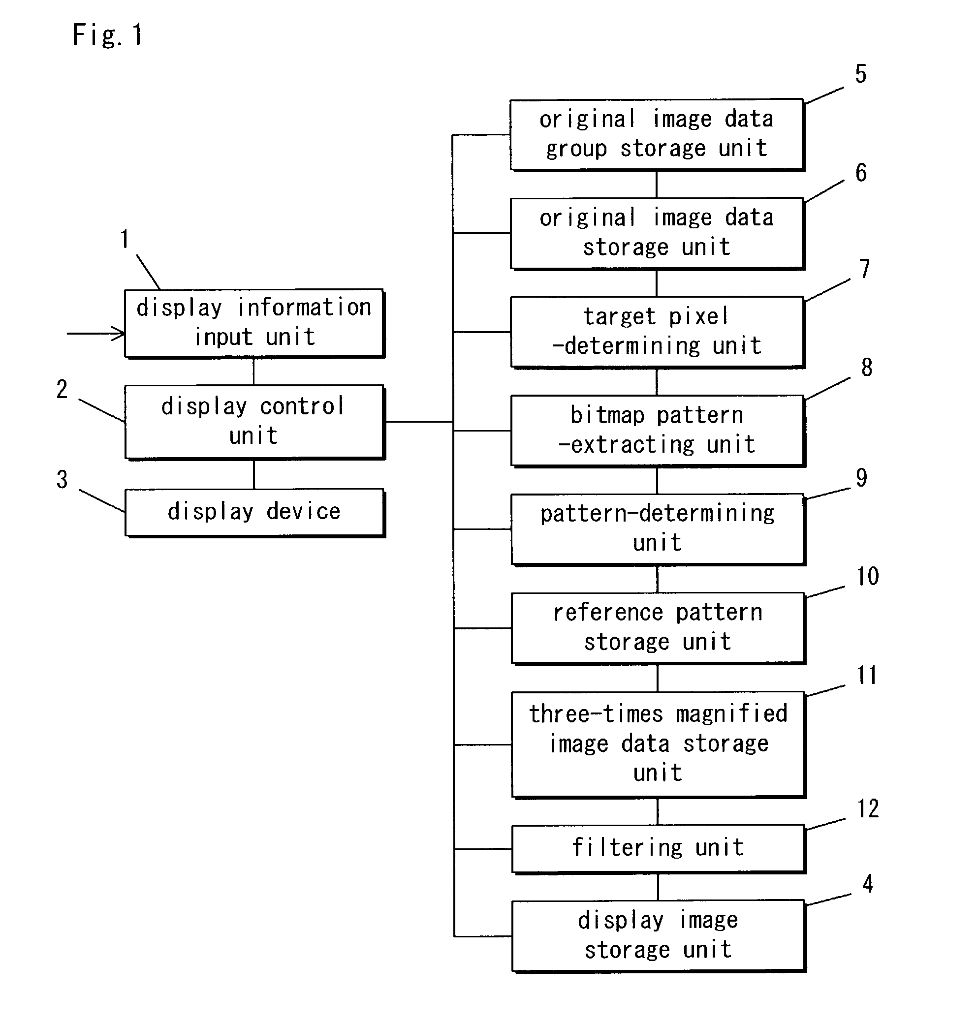
[0163]A first embodiment of the present invention is now described. FIG. 1 is a block diagram, illustrating display equipment according to the first embodiment.

[0164]Referring to FIG. 1, the display equipment includes a display information input unit 1, a display control unit 2, a display device 3, a display image storage unit 4, an original image data group storage unit 5, an original image data storage unit 6, a target pixel-determining unit 7, a bitmap pattern-extracting unit 8, a pattern-determining unit 9, a reference pattern storage unit 10, a three-times magnified image data storage unit 11, and a filtering unit 12.

[0165]In FIG. 1, the display information input unit 1 enters display information. The display control unit 2 controls all components of FIG. 1 in order to display an image on the display device 3 in accordance with a display image stored in the display image storage unit 4 (VRAM).

[0166]The display device 3 has three light-emitting elements aligned wit...

embodiment 2

(Embodiment 2)

[0336]A second embodiment is now described. Only the differences in structure from the previous embodiment are described. FIG. 20 is a block diagram, illustrating display equipment according to the present embodiment.

[0337]Different from the previous embodiment, the present embodiment determines a three-times magnified pattern and horizontally contiguously adjacent sub-pixel patterns next thereto on the basis of logic operation, not by storing three-times magnified pattern-determining rules. Therefore, as illustrated in FIG. 20, a pattern logic operation unit 13 is substituted for the reference pattern storage unit 10 of FIG. 1.

[0338]The following discusses an example in which a three-times magnified pattern and horizontally contiguously adjacent sub-pixel patterns next thereto are determined under the assumption of n=m=1 and x=y=1 when a target pixel is black.

[0339]The manner in which the pattern logic operation unit 13 performs logic operation is described below with...

embodiment 3

(Embodiment 3)

[0355]A third embodiment is now described.

[0356]FIG. 23 is a block diagram, illustrating display equipment according to the present embodiment.

[0357]As illustrated in FIG. 23, the display equipment includes a display information input unit 1, a display control unit 2, a display device 3, a display image storage unit 4, an original image data group storage unit 5, an original image data storage unit 6, a bitmap pattern-extracting unit 14, a pattern-determining unit 15, a reference pattern storage unit 16, a three-times magnified pattern-correcting unit 17, a three-times magnified image data storage unit 11, and a filtering unit 12. The same components as those of FIG. 1 are identified by the same reference characters, and descriptions related thereto are omitted.

[0358]The bitmap pattern-extracting unit 14 in FIG. 23 extracts a bitmap pattern from original image data stored in the original image data storage unit 6. The extracted bitmap pattern is identical in shape to a...


PUM

PropertyMeasurementUnit
line widthaaaaaaaaaa
colorsaaaaaaaaaa
sizeaaaaaaaaaa

Abstract

A three-times magnified pattern of a central target pixel and horizontally contiguously adjacent sub-pixel patterns next thereto are determined on the basis of a reference pattern that has a rectangular profile and further that consist of eight-neighboring pixel about the target pixel. The determined three-times magnified pattern is allocated to three sub-pixels that form the target pixel. The determined sub-pixel patterns are allocated to horizontally adjacent sub-pixels next to the target pixel. As a result, a black area defined by the target pixel is displaced rightward by an amount of a sub-pixel without any change in black area size that corresponds to three sub-pixels. This feature inhibits a variation in output image density, which otherwise would conspicuously occurs as a result of a varied object line width.

Description

BACKGROUND OF THE INVENTION[0001]1. Field of the Invention[0002]The present invention relates to display equipment and an art related thereto.[0003]2. Description of the Related Art[0004]Display equipment that employs various types of display devices have been in customary use. One known type of display equipment heretofore includes a display device such as a color LCD and a color plasma display, in which three light-emitting elements for illuminating three primary colors (RGB) are aligned in certain sequence to form a pixel. A plurality of the pixels are aligned in series in a first direction, thereby forming a line. A plurality of the lines are aligned in a second direction perpendicular to the first direction, thereby forming a display screen on the display device.[0005]A large number of display devices having display screens reduced in size to a degree that they fail to provide a sufficiently fine display. This problem is commonly seen in the display devices disposed in, e.g., a...

Claims


Application Information

Patent Timeline
Patent Type & Authority Patents(United States)
IPC IPC(8): G09G5/00G06K9/40G02F1/133G06T3/40G09G3/20G09G3/28G09G3/36G09G5/28G09G5/36H04N9/12
CPCG06T3/4007G09G5/227G09G5/391G09G2340/0457G09G5/00
Inventor TOJI, BUNPEITEZUKA, TADANORIYOSHIDA, HIROYUKI
Owner SOVEREIGN PEAK VENTURES LLC
Why Eureka
Try Eureka