Electronic timepiece and electronic apparatus

a technology of electronic equipment and electronic timepiece, which is applied in the direction of electric winding, instruments, and horology, can solve the problems of increasing the size of the battery compared, requiring more often replacement of the battery, and affecting the efficiency of the battery, so as to facilitate the reduction of the cost of components and facilitate the saving of space , the effect of preventing the effect of productivity declin

Inactive Publication Date: 2007-01-02
SEIKO EPSON CORP
View PDF13 Cites 18 Cited by
  • Summary
  • Abstract
  • Description
  • Claims
  • Application Information

AI Technical Summary

Benefits of technology

[0016]By such a structure, the antenna for receiving radio waves, the electromagnetic motor, and the power source are placed not to overlap in the thickness direction of the electronic timepiece. In the clock, the antenna, the motor, and the power source are components as components, being the largest in thickness, and if these components do not overlap in the thickness direction of the clock, the thickness of the electronic timepiece can be made thinnest. As a result, when making the electronic timepiece a portable clock such as a wrist clock, the design and installation characteristics can be improved.
[0078]To prevent the magnetic field from the generating coil from affecting the antenna, the generating coil and the antenna are preferably installed apart from each other as possible as they are. Therefore, if the generating coil and the antenna are installed on the opposite sides to each other with the hand axis of the hands to display time between them, the distance between the components can be extended. As a result, the magnetic field from the generating coil on the antenna can be decreased, and wireless information can be received by the antenna without the impact of the magnetic field.

Problems solved by technology

Such a radio wave clock is normally driven by a battery, but since power is consumed in receiving radio waves, the size of the battery is increased compared with that of a normal clock, and there is a problem of requiring more often replacement of the battery.
Further, there is a problem that its movement is also enlarged.
However, efficient solar power generation cannot be assured since it is dependent on conditions such as daylight amount (for example, cloudy or rainy weather), seasons (for example, winter), and regions (for example, high latitude region), and so it sometimes cannot supply power.
Because of this, if sufficient power is not supplied to the receiving mechanism, the standard radio waves cannot be received, or the standard radio waves are wrong-received, and therfore the receiving sensitivity of the receiving mechanism is decreased.
Further, there is a problem that rapid charge is impossible in the solar battery if a receiving light energy is weak.
Because of this, the radio wave clock having the solar power-generation mechanism is not necessarily a convenient clock.
Therefore, when standard radio waves are received by the antenna, if the magnetic field from the generating coil overlaps the antenna, the signal of the standard radio waves is deformed by the influence of the magnetic field, the standard radio waves cannot be received or are wrong-received.
That is, if a power-generation mechanism for converting mechanical energy to electrical energy is just simply installed inside the radio wave clock, there occurs a new problem that standard radio waves cannot be received.
Such a problem is not limited to an electronic timepiece having a radio wave correction function, and is a common problem which can be applied to various electronic apparatuses including a power-generation mechanism for converting mechanical energy to electrical energy and an antenna receiving wireless information from the outside.
However, since the components for the module and the placement with the antenna are not disclosed, it is difficult to make the radio wave clock thin.

Method used


Image

  • Electronic timepiece and electronic apparatus
  • Electronic timepiece and electronic apparatus
  • Electronic timepiece and electronic apparatus

Examples


example 1

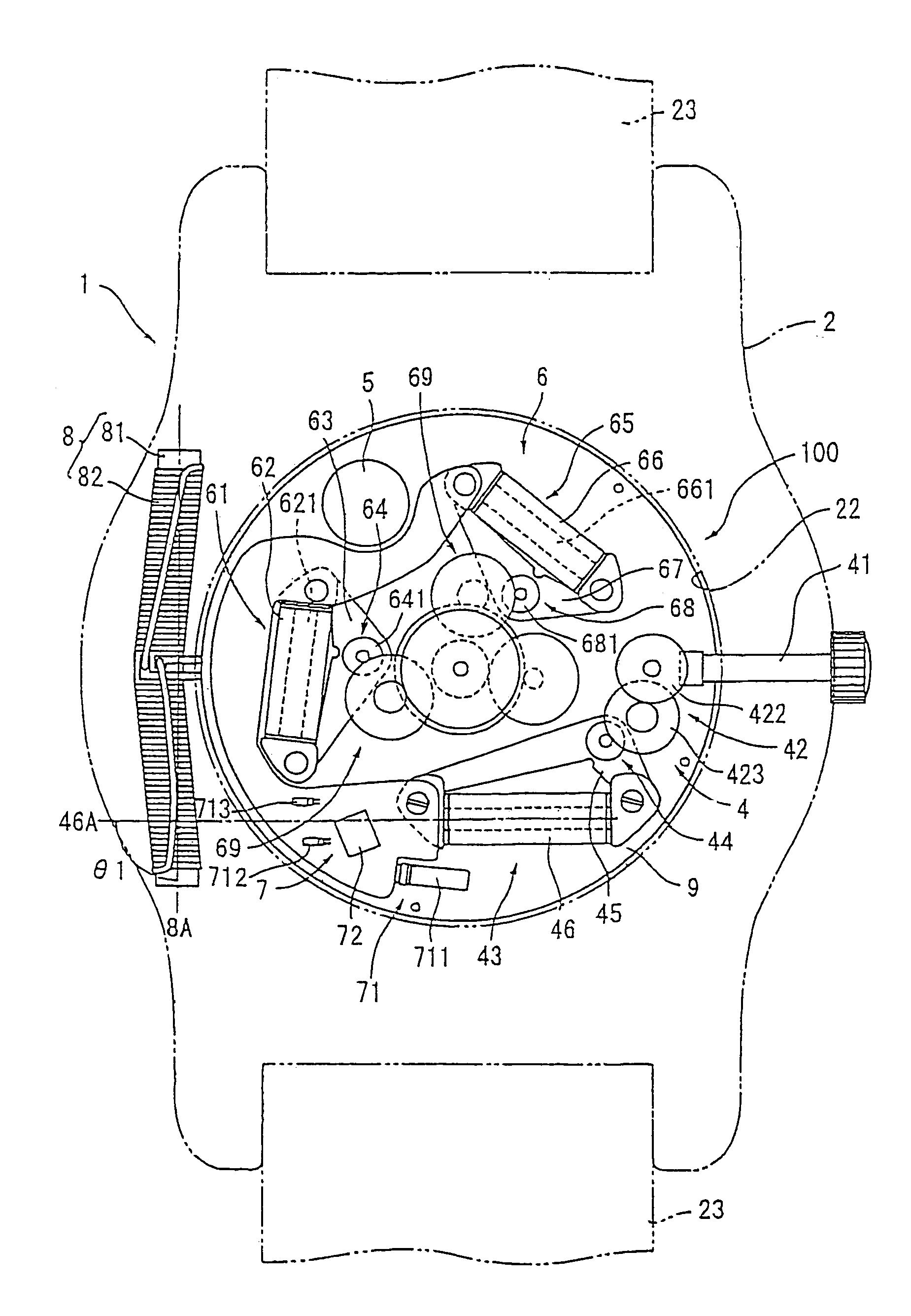
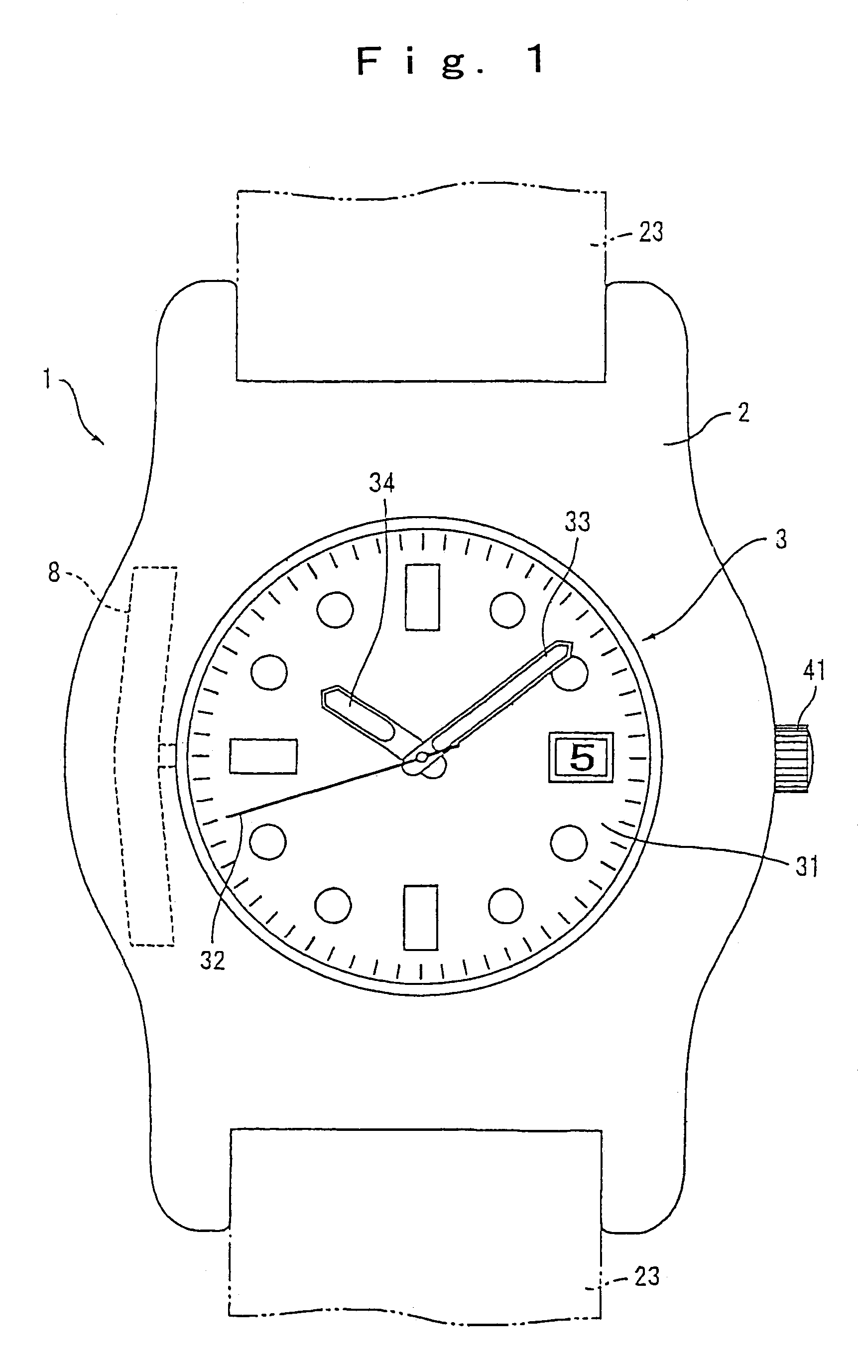
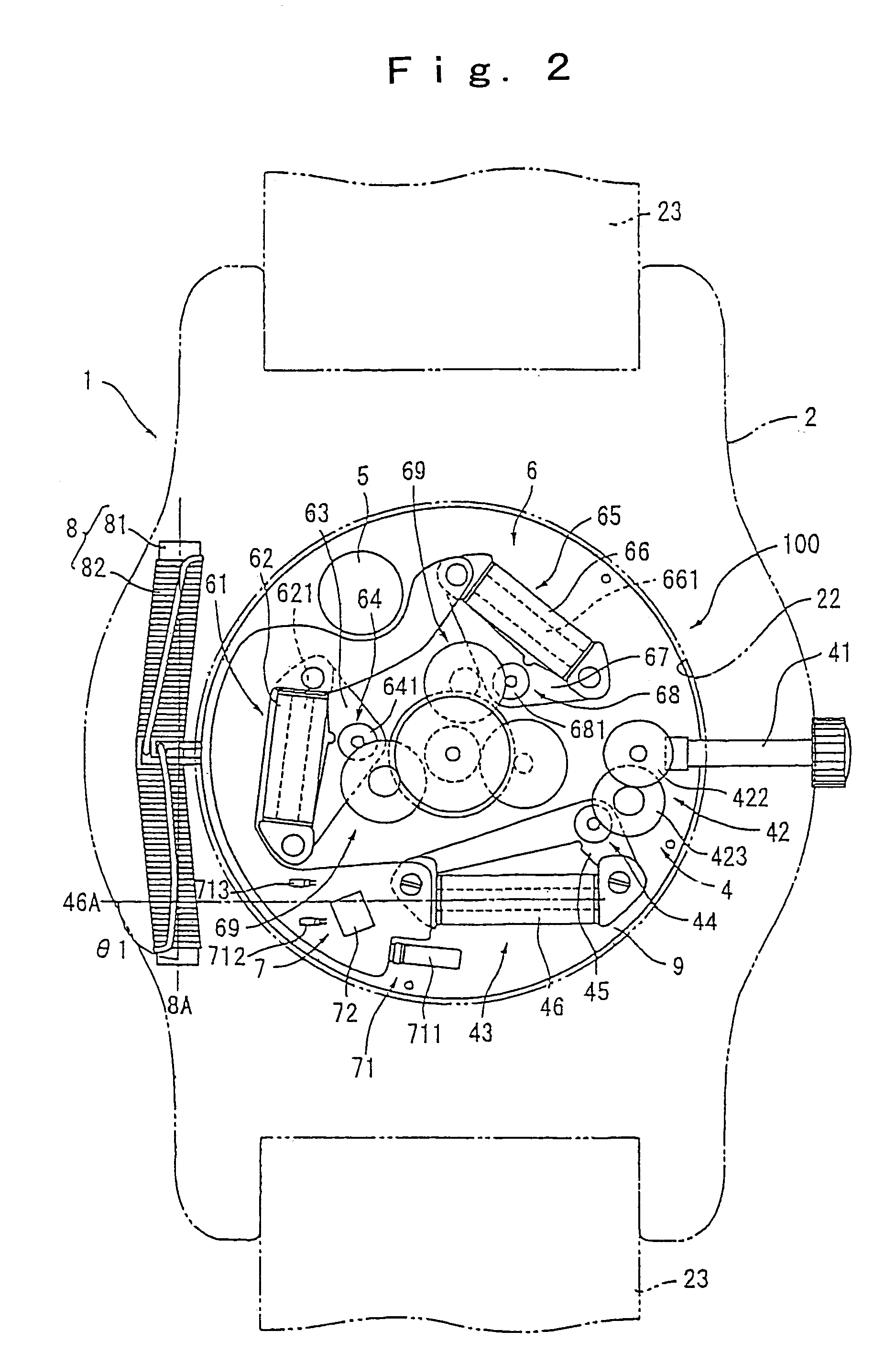
[0098]FIG. 1 is an outer view of a wristwatch-typed radio wave clock 1 according to the electronic timepiece and electronic apparatus of a first embodiment of the present invention. FIG. 2 is a view of the radio wave clock 1 with a back lid removed off.

[0099]The radio wave clock 1 includes a body case 2 as a base frame, a time-measuring movement 100 installed inside the body case 2, and an antenna 8 for receiving standard radio waves including time information as wireless information (radio-waves).

[0100]The body case 2 is substantially ring-shaped and composed of a non-conductive material such as synthetic resin or ceramic, etc., and of a diamagnetic material such as brass or gold alloy, etc., and there is a time display part 3 installed on the external surface of the body case 2, which is shown in FIG. 1. Attachment portions are provided respectively on the peripheral two opposite locations of the body case 2, for attaching a wristwatch band 23.

[0101]The time display part 3 include...

example 2

[0136]FIG. 4 illustrates a radio wave clock 1 of the electronic timepiece according to the second embodiment of the present invention. The basic structure of the radio wave clock 1 is the same as that of the first embodiment, and the placement of the antenna 8 and the coil 46 is different from the structure in the first embodiment. In this embodiment, the antenna 8 and the generating coil 46 are placed on the opposite side with a hand axis 35 of the hands (a second hand 32, a minute hand 33, and an hour hand 34) between them, and they are placed furthest apart from each other in the structure of the radio wave clock 1.

[0137]A secondary battery 5, a second hand driving motor 61, and a minute / hour hand driving motor 65 are placed between the antenna 8 and the power-generation coil 46. Therefore, magnetic field shielding means includes a coil core 621 of a coil for second hand motor 62, a coil core 661 of a coil for minute / hour hand motor, and the case of the secondary battery 5. The m...

example 3

[0142]FIG. 5 illustrates a radio wave clock 1 of the electronic timepiece according to the third embodiment of the present invention. The basic structure of the radio wave clock 1 is the same as that of the first embodiment. The structure of an intermediate gear of a power transmission part 42 of the third embodiment is different from that of the first embodiment.

[0143]FIG. 6 illustrates an intermediate gear 424 in this embodiment. The intermediate gear 424 is configured to include a first driving disk 425 engaged with a crown gear 422 and pressed-fit to the rotation axis, a first cylinder 426 pressed-fit to the rotation axis, a second cylinder 427 flexibly coupled to the rotation axis to rotate independently, a second driving disk 428 engaged with a power-generation rotor 44 and rotating integrally with the second cylinder 427, and a coil spring 429, the one end being fixed to the first cylinder and the other end being fixed to the second cylinder. Further, between the power-genera...


PUM


Abstract

An electronic timepiece includes a radio wave receiving antenna (8) for receiving radio waves, electromagnetic motors (61, 65) for driving a time display part, a battery (5), and a body case for receiving the antenna (8), electromagnetic motors (61, 65), and the battery (5). The antenna (8), electromagnetic motors (61, 65), and the battery (5) do not overlap as viewed in the viewing direction of a time display part, that is, they do not overlap two-dimensionally. By such a structure, the electronic timepiece can be thin and flat.

Description

TECHNICAL FIELD[0001]The present invention relates to an electronic timepiece and an electronic apparatus, and more specifically, it relates to an electronic timepiece and an electronic apparatus having a receiving mechanism for receiving wireless information.BACKGROUND ART[0002]As an electronic apparatus such as an electronic timepiece having a function for receiving wireless information, there is known, for example, a radio wave clock for receiving time information transmitted by wireless (standard radio waves) and performing time correction. Such a radio wave clock is normally driven by a battery, but since power is consumed in receiving radio waves, the size of the battery is increased compared with that of a normal clock, and there is a problem of requiring more often replacement of the battery. Further, there is a problem that its movement is also enlarged.[0003]Because of this, a radio wave clock having a solar power-generation mechanism installed as a generating mechanism is...

Claims


Application Information

Patent Timeline
Patent Type & Authority Patents(United States)
IPC IPC(8): G04C11/02G04B1/00G04F5/00G04C3/14G04C3/00G04C10/00G04G21/04G04R20/00G04R20/08G04R60/02G04R60/10
CPCG04C3/008G04R60/10G04G21/04G04C3/14G04R60/02
Inventor FUJIMORI, SHIGEYUKIKITAHARA, JOJI
Owner SEIKO EPSON CORP
Why Eureka
Try Eureka