Focus control for optical disk unit

a technology of optical discs and focus control, which is applied in the direction of data recording, instruments, disposition/mounting of heads, etc., can solve the problems of disc colliding with the objective lens, affecting the speed of the collision between the objective lens and the optical disc surface, and the object lens actuator of the optical head runs out of control,

Inactive Publication Date: 2007-01-02
PANASONIC CORP
View PDF14 Cites 8 Cited by
  • Summary
  • Abstract
  • Description
  • Claims
  • Application Information

AI Technical Summary

Benefits of technology

[0016]Information indicating the reflectance of the information recording layer may be formed beforehand on the surface of the protective layer, the control means may read the information from the surface of the protective layer while the focus control to the surface of the protective layer is performed, and may set the feed back gain of the focus control to the surface of the information recording layer based on the information.
[0018]The present invention provides an optical disc unit for an optical disc having one or more information surfaces having a plurality of tracks formed thereon, comprising: tracking error detection means for detecting a misalignment between an optical beam applied to the optical disc and one of the plurality of the tracks corresponding thereto, and outputting a tracking error signal indicating the misalignment; amplification detection means for detecting amplification of the tracking error signal; focus control means for performing focus control such that a distance between a focal point of the optical beam and the information surface is within a predetermined error limit; shift means for shifting the position of the focal point of the optical beam toward the optical disc; and control means for controlling the focus control means and the shift control means, wherein the control means controls the shift means such that the focal point of the optical beam is shifted in a direction traversing tracks formed on the information surface of the optical disc and approaches the optical disc with an operation of the focus control means stopped; and the control means allows the focus control means to start the operation only when the amplification of the tracking error signal is detected to become a predetermined value or higher by the amplification detection means, thereby achieving the above-described objectives.
[0022]The control means may control rotations of the optical disc such that the number of rotations of the optical disc when the amplification of the tracking error signal is detected by the amplification detection means is smaller than the number of rotations of the optical disc when information recorded on the information surface of the optical disc is being reproduced.
[0029]The focus control means may set a gain such that the gain is smaller, compared to when information recorded on the optical disc is being reproduced, for a predetermined period after the focus control means has started the operation.

Problems solved by technology

Once the focus is out of control, an objective lens actuator of an optical head runs out of control and may crash into the optical disc surface.
However, the conventional method has the problem of an increased rate of collision between an objective lens and the optical disc surface in the case where a working distance of the objective lens (the distance between the objective lens and the optical disc surface) is smaller than the wobbling of the optical disc.
However, if it fails, even though the objective lens actuator does not run out of control, in the case where the wobbling of the disc is greater than the working distance, there is a possibility that the disc collides into the objective lens.
However, if the NA is raised to its limit in order to further increase the recording capacity in the future, the designed working distance of the objective lens becomes extremely small.
However, when the focal point passes the optical disc surface, the focus error signal also crosses zero.
Thus, it is difficult to distinguish the optical disc surface and the information surfaces based on the total internal reflection amount.
This means that it is difficult to ensure the focusing to the information surface if the focusing is performed in a method similar to the conventional method.

Method used


Image

  • Focus control for optical disk unit
  • Focus control for optical disk unit
  • Focus control for optical disk unit

Examples


embodiment 1

(Embodiment 1)

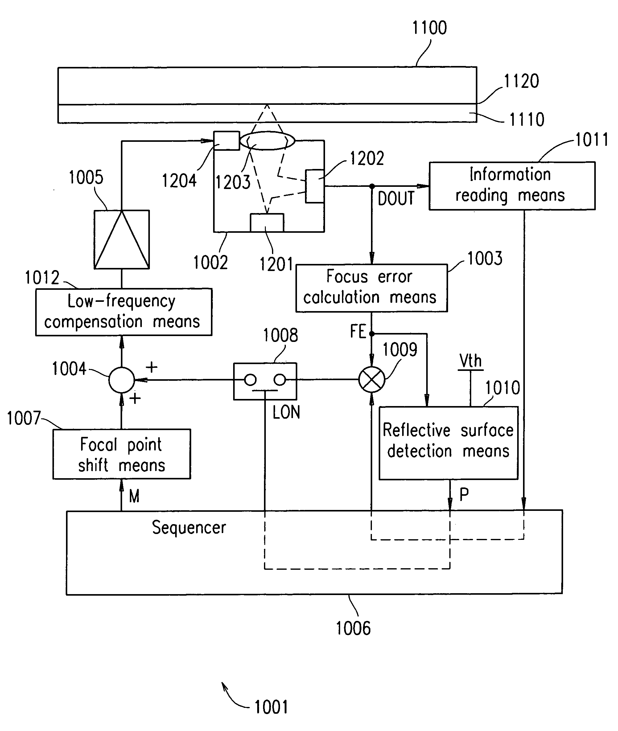
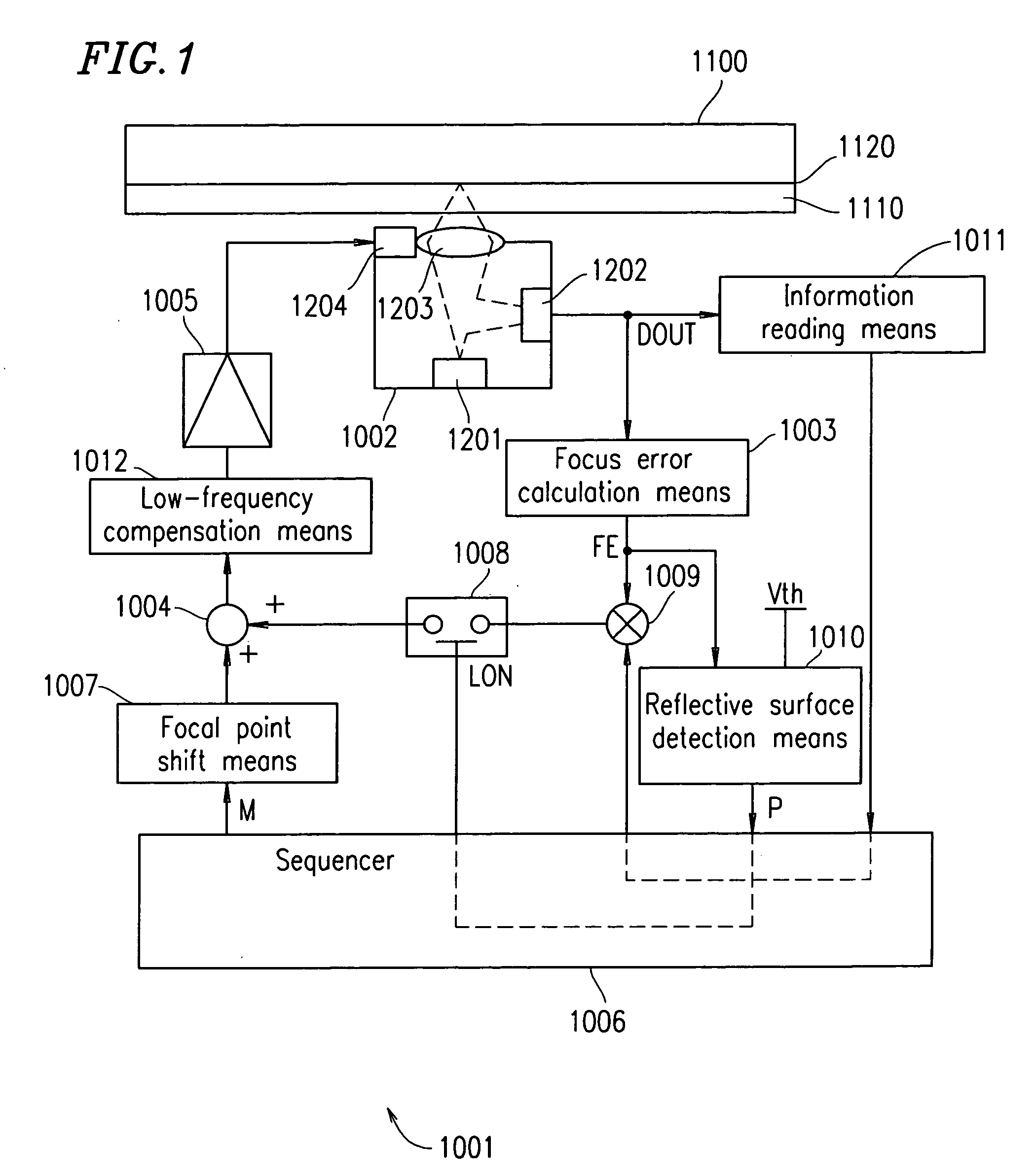
[0072]FIG. 1 shows an exemplary structure of an optical disc unit 1001 according to Embodiment 1 of the present invention.

[0073]The optical disc unit 1001 records information on an optical disc 1100 and reproduces information recorded on the optical disc 1100. The optical disc 1100 has an information recording layer 1120 and a protective layer 1110 formed on the information recording layer 1120.

[0074]The optical disc unit 1001 includes an optical head 1002 for irradiating the information recording layer 1120 with a convergence laser beam.

[0075]The optical head 1002 includes a laser light source 1201, light receiving means 1202, an objective lens actuator 1204, and an objective lens 1203.

[0076]The laser light source 1201 outputs a laser beam. The laser beam output from the laser light source 1201 is focused with the objective lens 1203. As a result, the optical disc 1100 is irradiated with the convergence laser beam. The convergence laser beam reflected off the optical ...

embodiment 2

(Embodiment 2)

[0109]FIG. 4 shows an exemplary structure of the optical disc unit 2002 according to Embodiment 2 of the present invention.

[0110]In the present embodiment, a photodetector 2113 and a TE signal generation circuit 2102, which will be described later, act as tracking error detection means. The tracking error detection means detects a misalignment between an optical beam applied to an optical disc 2100 having an information surface with a plurality of tracks formed thereon and one of the tracks which corresponds thereto, and outputs a tracking error signal which indicates the misalignment.

[0111]The photodetector 2113, an FE signal generation circuit 2115, a phase compensation circuit 2116, a power amplifier 2118 and an actuator 2104 act as focus control means. The focus control means performs a focus control such that a distance between a focal point of the optical beam and the information surface of the optical disc 2100 is within a predetermined error limit.

[0112]A micro...

embodiment 3

(Embodiment 3)

[0146]FIG. 10 shows an exemplary structure of an optical disc unit 2003 of Embodiment 3. In FIG. 10, like blocks as in the above embodiments are indicated by like reference numerals, and the explanations thereof are omitted.

[0147]FIG. 11 shows a plurality of tracks formed on an information surface of an optical disc 2150. Each of the tracks is wavy. In the exemplary structure shown in FIG. 11, each of the tracks slightly wobbles in a radial direction thereof with a predetermined period W. These slight wobbles can be detected by the TE signals as a misalignment between the optical beam 2106 and the tracks. The optical disc 2150 may be a single-layer disc, or a multilayer disc, including a doublelayer disc.

[0148]FIG. 12 shows waveforms of the signals when the optical beam 2106 traverses the tracks with the focus control being performed, wherein (a) schematically represents the tracks. Waveform (b) represents a TE signal. Waveform (c) represents an output from a BPF 2151....


PUM

PropertyMeasurementUnit
reflectanceaaaaaaaaaa
distanceaaaaaaaaaa
thicknessaaaaaaaaaa

Abstract

An optical disc unit 2001 comprises: reflective surface detection means 1010 for detecting a reflective surface; focus control means (1202, 1003, 1009, 1008, 1003, 1012, 1005 and 1204) for performing focus control to a reflective surface so that the distance between the focal point of an optical beam applied to an optical disc 2100 and the reflective surface is within a predetermined error limit; shift means 1007 for shifting the focal point of the optical beam in a direction perpendicular to the optical disc; and control means 1006 for controlling the focus control means and the shift means.

Description

TECHNICAL FIELD[0001]The present invention relates to an optical disc unit for recording information such as digital video information on an optical disc in high density and reproducing information recorded on an optical disc, and in particular, an optical disc unit which is capable of performing an accurate focus control to an information surface of an optical disc.BACKGROUND ART [0002]Recently, optical discs have been drawing attention as exchangeable media with a high capacity and an optical disc unit is expected to be used more widely as a video recorder in the future. One of the reasons why the optical disc is a high-capacity exchangeable medium is that it allows performance of recording / reproduction without contacting the medium. In other words, a laser beam is focused and an information recording layer of an optical disc is irradiated with the focal point thereof, and thus recording and reproduction are performed. Therefore, even when some dirt or dust is adhered on the surfa...

Claims


Application Information

Patent Timeline
Patent Type & Authority Patents(United States)
IPC IPC(8): G11B7/095G11B7/00G11B7/085
CPCG11B7/08511G11B2007/0013G11B7/09
Inventor ISHIBASHI, HIROMICHIWATANABE, KATSUYAFUJIUNE, KENJIYAMADA, SHINICHIKUZE, YUUICHI
Owner PANASONIC CORP
Why Eureka
Try Eureka