Drive train for a header of a harvesting machine

a technology for harvesting machines and drive trains, which is applied in the direction of auxiliary drives, mowers, control devices, etc., can solve the problems of large time-consuming, complicated and cost-intensive drive shafts, and the drive shaft must provide a relatively large area for angle and length change, so as to achieve the effect of large possible rang

Inactive Publication Date: 2007-01-09
MASCHFAB KEMPER
View PDF20 Cites 32 Cited by
  • Summary
  • Abstract
  • Description
  • Claims
  • Application Information

AI Technical Summary

Benefits of technology

[0017]However, particularly for such headers, it is proposed to align the drive shaft at least approximately in the direction of travel or within a range of angles up to approximately 45° forward. This produces a compact arrangement of the drive shaft and a large possible range of pendulum angles, so that the header can also be used on combines or other harvesting machines with slope equipment. In th

Problems solved by technology

Before the cutting system can be separated from the combine for transport, the drive shaft is manually removed from the feeder house and reattached before receiving another header, which represents a significant expense of time.
Due to the rather small amount of available space, particularly for swinging headers, which are attached to a combine with suspension equipment, it can be considered a disadvantage that the drive

Method used


Image

  • Drive train for a header of a harvesting machine
  • Drive train for a header of a harvesting machine
  • Drive train for a header of a harvesting machine

Examples


Embodiment Construction

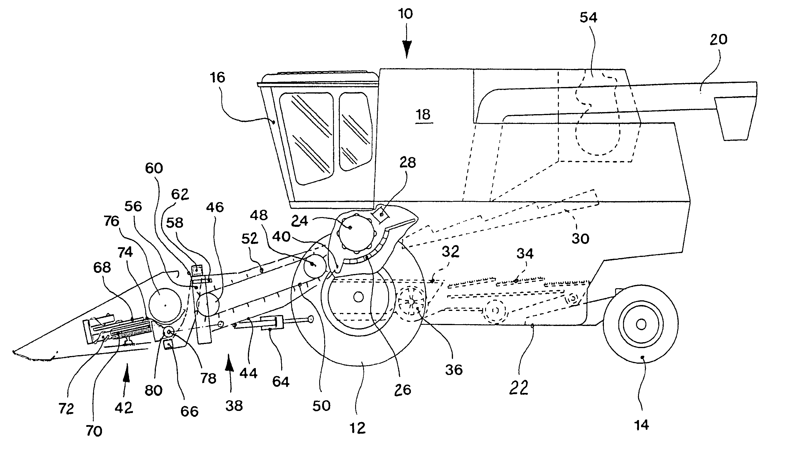
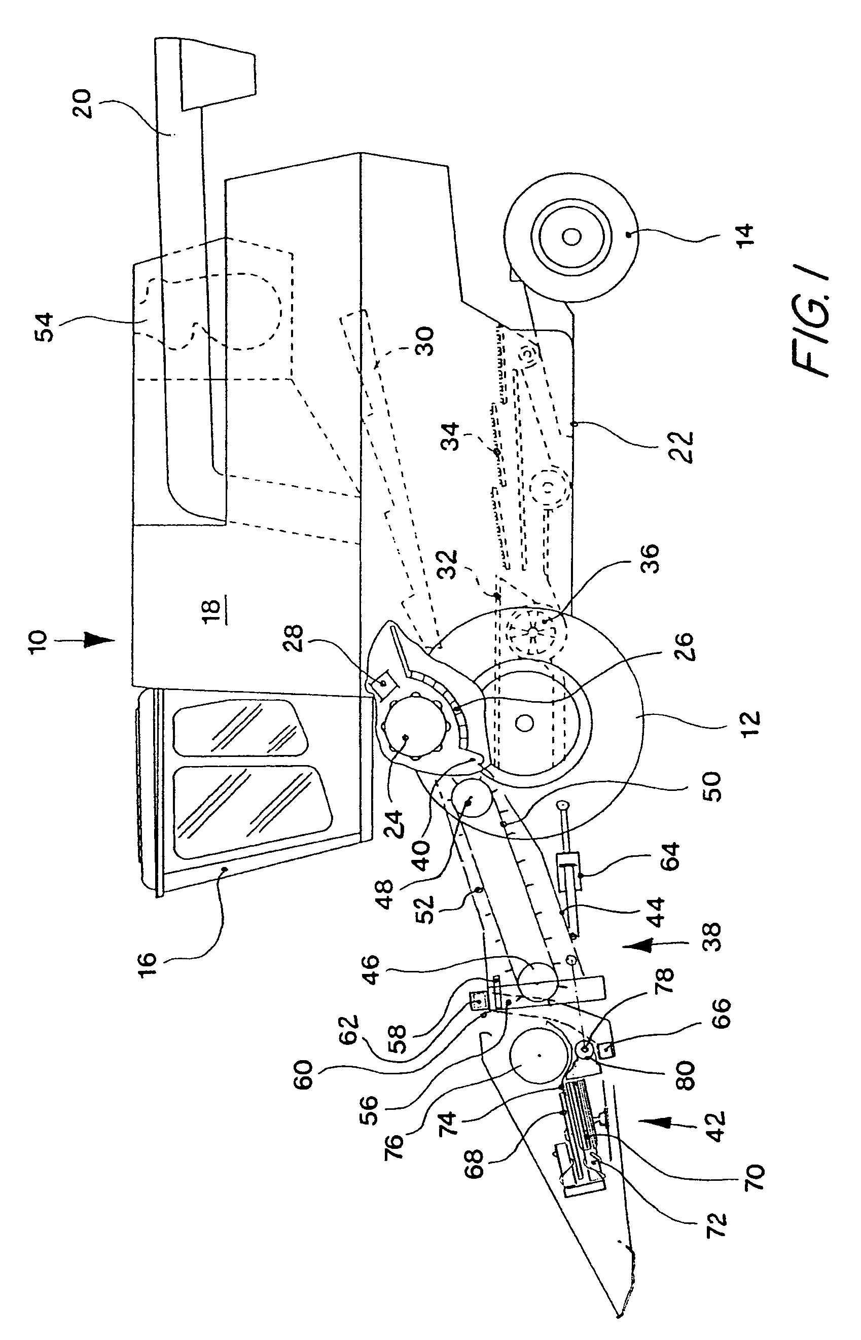
[0023]In the following description, the convention is used that directional information, such as forwards, backwards, and sideways, is relative to the direction of forwards travel of the harvesting machine. A harvesting machine shown in FIG. 1 in the form of a combine 10 is supported on front-wheel drive and rear-wheel steering wheels 12 and 14, respectively, and has a driver cabin 16, from which the machine can be operated by a driver. A grain tank 18 is located behind the driver cabin 16. The grain located in the grain tank 18 can be discharged therefrom by a discharge auger 20. The driver cabin and the grain tank 18 are supported on a frame 22. Harvested crop material is broken down into large and small components by a threshing assembly comprising a threshing cylinder 24, a threshing concave 26 and a beater 28. Trapped grain is separated from the threshed crop mat by a separating assembly comprising the illustrated straw walkers 30. The large non-grain crop components of the sep...


PUM


Abstract

A drive train for a header of a harvesting machine comprising a variable length drive shaft. The variable length drive shaft has a first end having a first hinged connection which is connected via a drive element with a first shaft. The variable length drive shaft has a second end having a second hinged connection that is operatively coupled to a driven element in driving connection with a drive shaft of the header. The drive shaft drives harvesting elements of the header. A connection element is arranged to align the drive element and the driven element at least approximately parallel to each other.

Description

FIELD OF THE INVENTION[0001]The present invention is directed to a drive train for a header of a harvesting machine, comprising a variable length drive shaft, which has a first end with a hinged connection connected via a drive element with a first shaft and a second end with a second hinged connection that can be brought via a driven element into a driving connection with a drive shaft of the header.BACKGROUND OF THE INVENTION[0002]In the prior art, cutting systems for combines are usually driven by drive shafts, which extend between a header drive shaft, which is coupled to the lower feeder house roller, and one or both lateral ends of the header, i.e., essentially perpendicular to the direction of travel (see DE 199 18 550 A). Telescoping drive shafts are used if the cutting system is to complete a pendulum motion about a horizontal axis in the direction of travel on its suspension on the feeder house. Before the cutting system can be separated from the combine for transport, the...

Claims


Application Information

Patent Timeline
IPC IPC(8): A01D34/03A01D69/00B60K25/06
CPCA01D69/00A01D41/142B60K25/06
Inventor RICKERT, CLEMENS
Owner MASCHFAB KEMPER
Why Eureka
Try Eureka