Tank piston seal and stabilizing system

a technology of stabilizing system and piston, which is applied in the direction of liquid transfer devices, instruments, volume meters, etc., can solve the problems of material leakage, material itself should be fully discharged, and the piston cannot drive all of the material towards the outlet,

Active Publication Date: 2007-01-09
PISTON TANK CORP
View PDF7 Cites 9 Cited by
  • Summary
  • Abstract
  • Description
  • Claims
  • Application Information

AI Technical Summary

Benefits of technology

[0012]A generally cylindrical tank piston rides within a cylindrical tank. The outer circumferential edge of the piston is slightly smaller than the inner circumference of the tank cylinder. A flexible seal is provided between the piston and the tank. The seal may be expanded or reduced in thickness to seal the piston and the inner surface of the tank cylinder. The front leg of the seal is double banded to prevent to the front of the seal from tearing away from the metal lip of the piston. A 60 durometer block of hard polyurethane is also provided to prevent any part of the seal from caving in. The compression mechanism comprises a single, sliding T-section adjacent to the rear leg of the seal. The unitary T-section may be tightened by a compression spring to conform the upper seal surface to the lower surface of the tank cylinder. Two parallel sets of stabilizing shoes help to keep the radial axis of the tank and piston aligned. These shoes have a counterclockwise spring and a clockwise spring to prevent coil binding of the springs as the springs are compressed. By increasing the strength of the springs from those commonly used in the industry (from 40 pounds to 160 pounds) and by using an inside wound clockwise and an outer wound counterclockwise spring, the problem of coil binding is eliminated.

Problems solved by technology

In this particular field, one common problem encountered is the failure of the piston to drive all of the material towards the outlet as the piston moves towards the outlet.
Another drawback is that the material itself should be fully discharged and the piston should have cleaning and wiping action as it moves.
However, many problems are associated with this type of seal and many attempts have been made to perfect the seals.
However, often these commonly used prior art seals will tear away from the piston head, causing leakage of the material and an imperfect seal.
Another problem encountered in this art but not yet solved, is that the seal, when totally compressed, becomes concave, thus reducing the effectiveness of the seal.
Yet another problem with the prior art seals is that compressing the flexible piston seal creates a binding effect which, in turn, causes the seal to move vertically up or down in an erratic, rather than smooth, fashion.
However, these anti-canting devices often times become “coil bound”.
The springs used heretofore were too weak to accomplish the function correctly.
It has been found that springs of 40 pound strength were too small to function properly.

Method used


Image

  • Tank piston seal and stabilizing system
  • Tank piston seal and stabilizing system
  • Tank piston seal and stabilizing system

Examples


Embodiment Construction

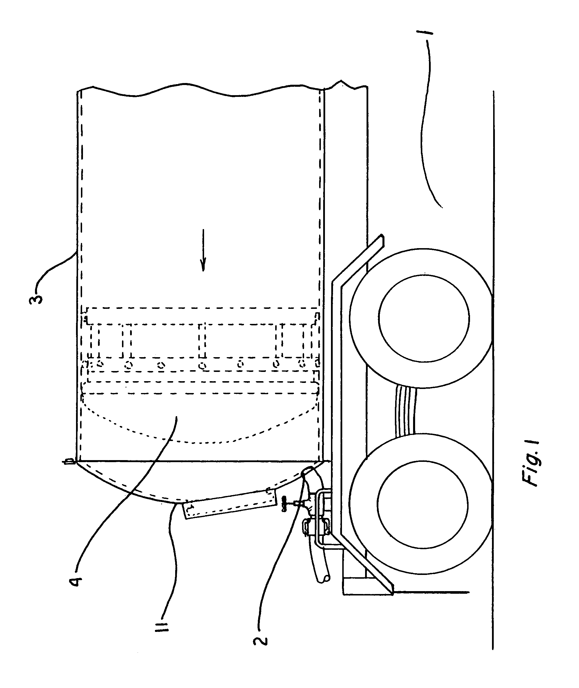
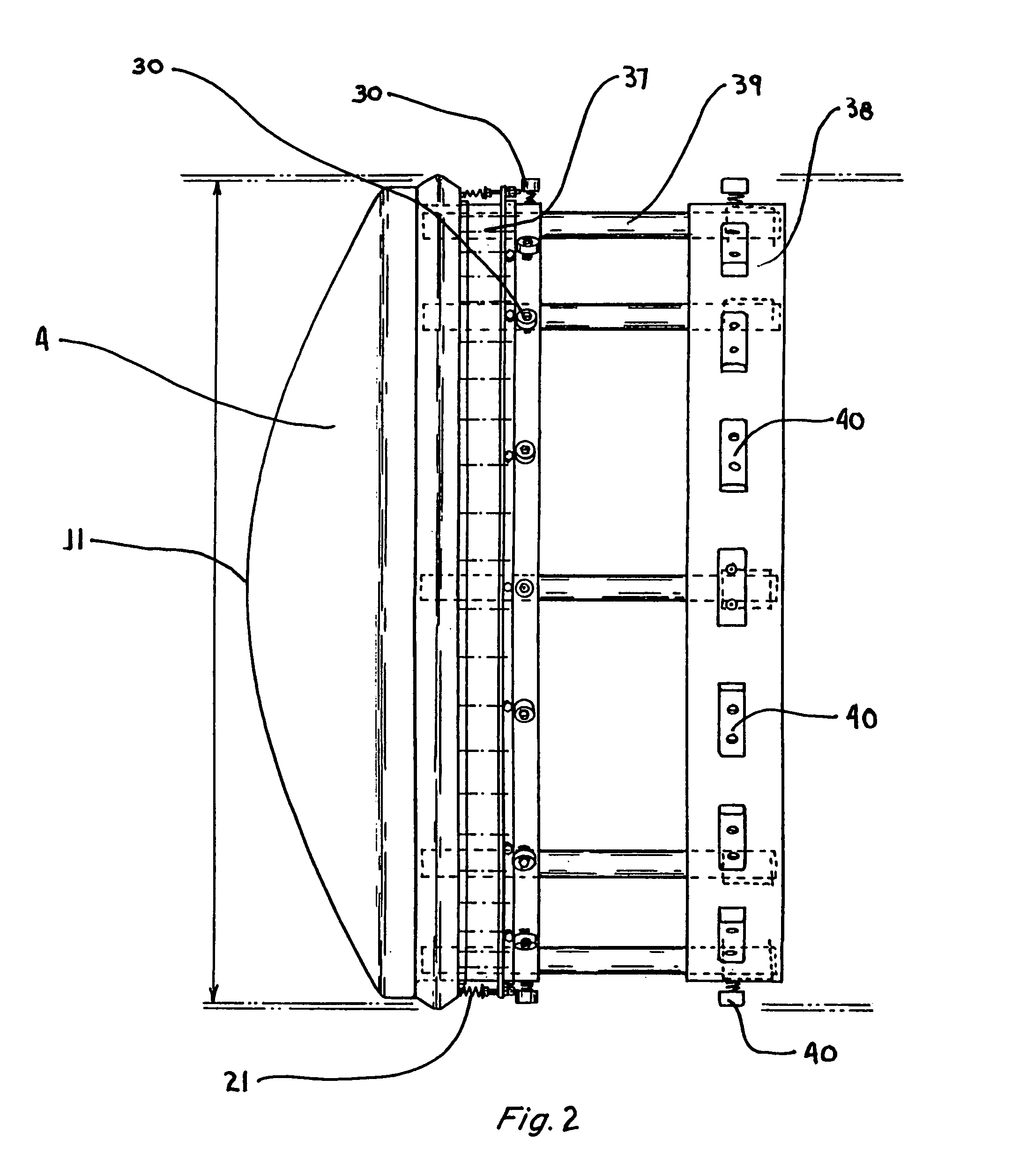
[0021]Heavy viscous material such as chocolate or peanut butter is transported in a tractor-trailer 1 as best shown in FIG. 1. This tractor-trailer has an inlet / outlet 2 near one end of the outer container shell or tank cylinder 3. Located within the tank cylinder 3 is a piston head 4. The general irregularly shaped parts of the piston head are also shown in FIGS. 2 and 3. The front surface of the piston is curved, and tapers outwardly to a larger circular cross-section. The sides and rear of the piston head are flat and a smaller cylindrical rear head body is integral with the front of the piston head. The piston head 4 moves axially in the tank 3. The circular cross-section of the tank 3 is slightly larger than the outer diameter of the largest circular cross-section of the piston head. A sealing mechanism is described below that includes the piston head, seal, and supporting and tightening elements.

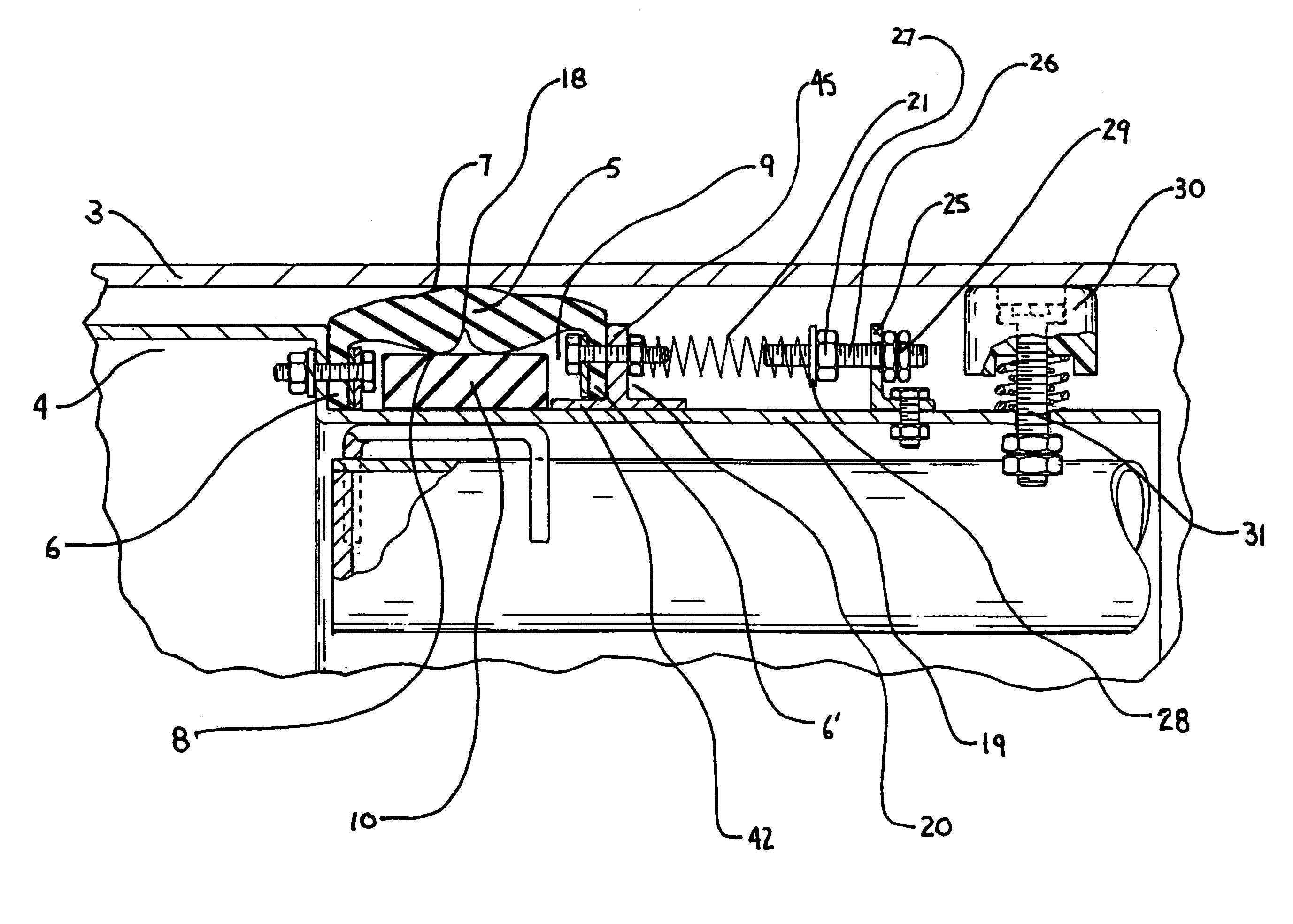
[0022]Turning to FIG. 4, the internal flexible seal 5 is shown. This flexible seal...


PUM


Abstract

An improved seal and stabilizing system for a piston head in a tank cylinder provides a better mechanism for discharging and wiping a cylinder when heavy liquids such as chocolate or peanut butter are being dispensed. The seal system now includes a free-floating block inside the seal and grooves in the inner lower part of the hollow seal. The block and grooves keep the upper, outer part of the seal from deforming away from the inner surface of the cylinder that facilitates complete discharging and wiping of the material from the cylinder tank. The tensioning mechanism of the seal is made from a unitary and annular ring T-ring that easily slides on the rear surface of the piston head. In order to stabilize the movement of the piston head down the cylinder, clockwise and counterclockwise springs are provided for the stabilizing shoes. The dual spring arrangement prevents coil binding of the springs. The springs and stabilizing shoes maintain the piston head cross section parallel to the cross section of the cylinder.

Description

BACKGROUND OF THE INVENTION[0001]This invention relates to the field of fluid transportation and dispensing. More particularly, fluids and thick viscous materials are dispensed from a tanker truck by means of an air-powered piston. A new and improved seal and stabilizing system is described.[0002]In the manufacturing field of transporting liquids or viscous materials such as oil, chocolate, peanut butter, or other thick materials, large trucks are often used. The truck tanks have a generally circular cross section and are cylindrical in form. The long tank cylinder has an outlet / inlet at one end, usually the far rear end of the tanker trailer and tractor combination. A thick viscous material may be loaded into the generally cylindrical tank at the inlet port. As the material is loaded, a piston, which generally has a shape identical to the circular cross section of the tank cylinder, is pushed towards the rear of the cylinder by the material being loaded. In this instance, the rear ...

Claims


Application Information

Patent Timeline
Patent Type & Authority Patents(United States)
IPC IPC(8): B67D5/42F16J1/06B67D7/60
CPCF16J15/56F16J15/3208
Inventor BIRSNER, MICHAEL F.
Owner PISTON TANK CORP
Why Eureka
Try Eureka