Multi-application wood working knife and clamping assembly

a multi-application, woodworking technology, applied in the field of forest industry, can solve the problems of reducing the cutting accuracy of wood working knives, etc., to achieve the effect of reducing the risk of twisting or displacement during use, reducing the risk of slipping, and being easy to adap

Inactive Publication Date: 2007-01-09
IGGESUND TOOLS
View PDF41 Cites 24 Cited by
  • Summary
  • Abstract
  • Description
  • Claims
  • Application Information

AI Technical Summary

Benefits of technology

[0021]Therefore, what is desired is a knife and a cooperating clamping assembly in which the knife can preferably be precisely positioned every time it is installed, even under difficult or awkward conditions. Also, the knife and clamping assembly will each preferably be designed so as to reduce the risk of twisting or displacement during use. Most preferably, the knife and clamping assembly will be more easily adaptable to different loading and dimensional requirements, so that one design can be used in many applications. As well, what is preferred is a knife that can be easily reground to a certain degree for those applications in which limited regrinding may be advantageous.

Problems solved by technology

The wood being processed is moved into the path of the rotating knives and the blade contacts the wood at a depth and orientation that results in the formation of wood chips, shavings, wafers, or strands.
Common to all the aforementioned machines is that the repetitive contact between the cutting edge of the knife and the wood causes the cutting edge to wear and become dull over time.
When the knife becomes too dull, it ceases to cut the wood cleanly and effectively.
For example, in chippers, waferizers, and veneer lathes, a dull knife results in chips, wafers, or veneer of reduced quality and / or inconsistent size.
However, this approach suffers from a number of known limitations.
This regrinding results in a change in size of the blade that if left unadjusted, would result in an altered location of the cutting edge after each regrinding.
Unless the position of the knife is adjusted in the clamping assembly each time, which is difficult to do accurately and is also time consuming, the performance achieved with the machine is degraded, sometimes to unacceptable levels.
Another limitation of this approach is that the grinding may not be sufficiently precise.
Equipment utilized within wood processing facilities is often such that accurate form (shape and angle) of the cutting edge cannot be maintained.
Furthermore, during the on-site regrinding, the knives are sometimes damaged, whether through overheating or other grinding process irregularities.
This can reduce the quality of the cutting edge causing the knife to wear faster degrading performance.
Similarly, deviations in the form of the cutting edge can also result in a reduction in performance.
However, this solution also has some drawbacks.
In these situations, many of the profiles of the disposable blades lack an efficient and cost-effective method for restoring the cutting edge without significantly altering the shape and position of the cutting edge upon reinstallation into the clamping assembly.
Another problem that affects knives used in many types of wood processing machines is the difficulty in securing the knives in the clamping assemblies under the action of the cutting forces.
The problem is most prevalent with disposable blade designs where the requirement for cost effectiveness and competitiveness mandates that the blades be compact and lightweight.
Such compact blades are often difficult to secure in the clamping assembly such that they can resist the various types of loads encountered across the different types of applications.
With chipper edgers and chipper canters, the face or finishing knives can often encounter significant loads directed to the topside of the cutting edge.
One particular problem that affects knife designs is the unsymmetrical nature of the loads distributed along the knife length.
In such situations, twisting may occur.
This difference in force along the length of the blade creates a torque on the knife which, if sufficiently large, can cause the knife to displace or twist in its mounting.
A problem is to provide a knife and mounting assembly which is capable of handling such twisting forces.
Under such circumstances, precise positioning may be difficult, simply because the required precision may be greater than is possible in a manual operation.
In many cases, the knives are changed in situations that are physically awkward for the person changing the knife.
This renders precise positioning even more difficult.
However while helping to maximize the accuracy of position of the cutting edge during initial installation, this approach does not minimize the chances for subsequent displacement when subjected to load.
Another issue in this field is the requirement for many different clamping assemblies and knives for the many different types of wood working applications.

Method used


Image

  • Multi-application wood working knife and clamping assembly
  • Multi-application wood working knife and clamping assembly
  • Multi-application wood working knife and clamping assembly

Examples


Embodiment Construction

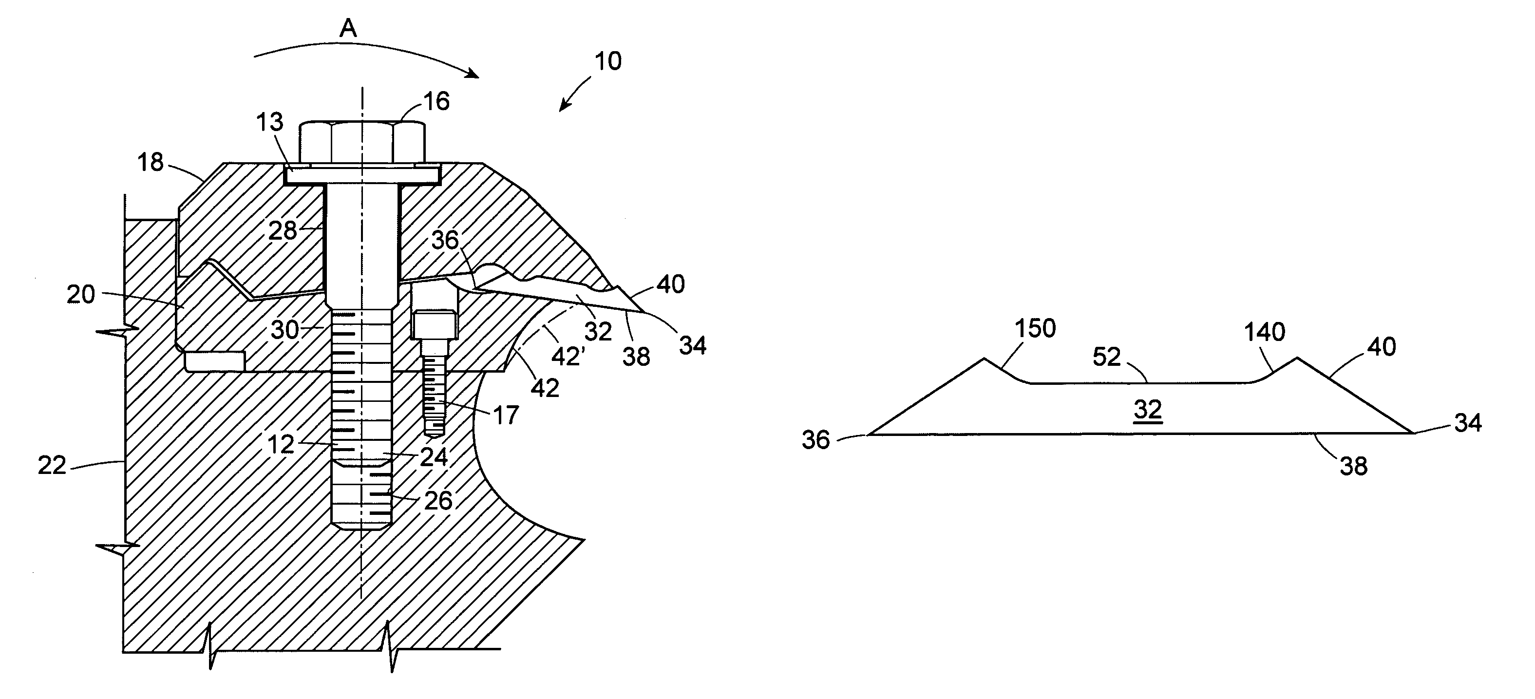
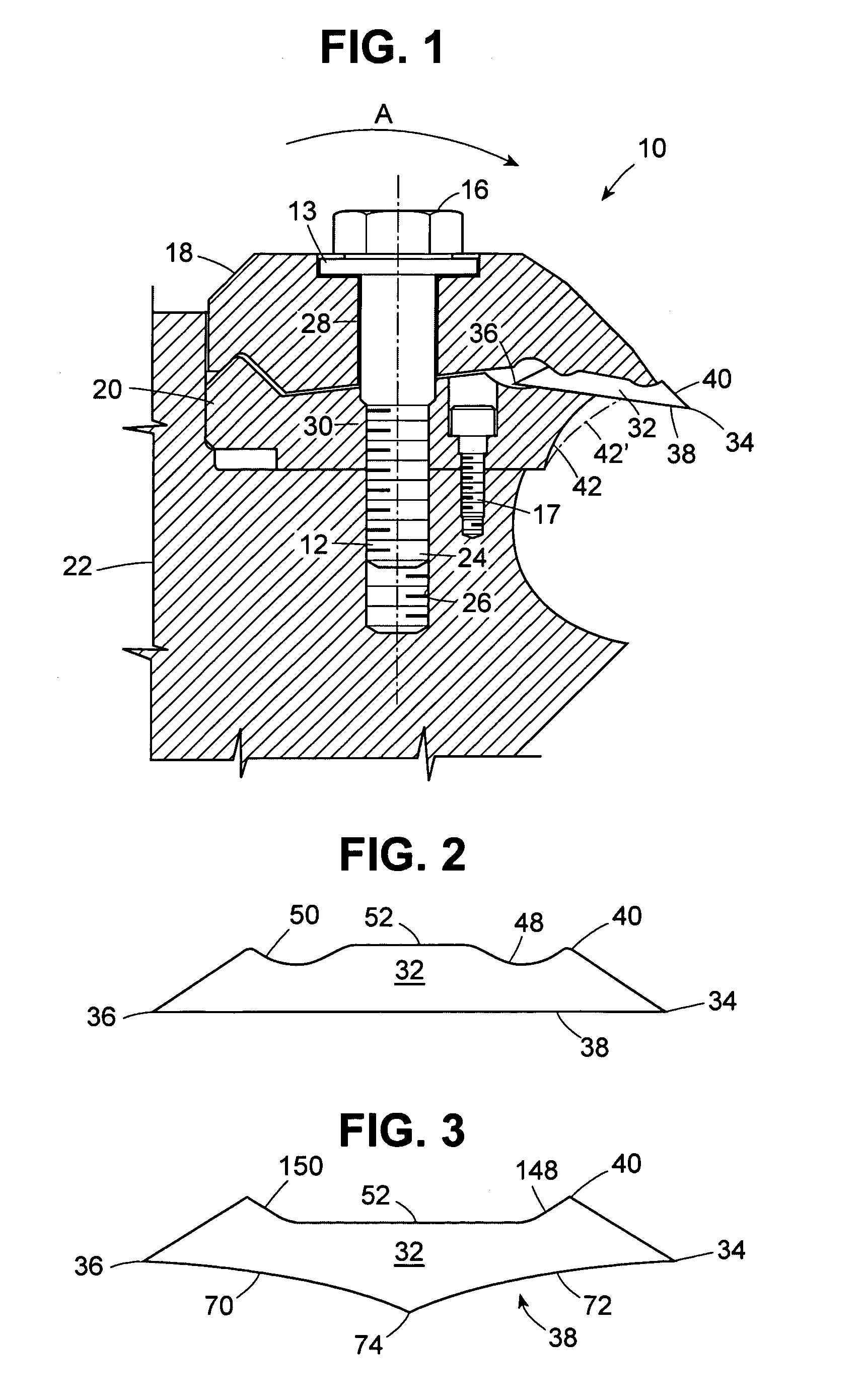
[0049]FIG. 1 shows a knife clamping assembly indicated generally by reference numeral 10 clamping a knife 32. The knife clamping assembly 10 is mounted on a base 22 which may be any form of disc, drum, hub, or other base member, as may be used in chippers, chipper-canters, planers, waferizers, or other machines of the type used to process wood to form lumber, chips, veneer or wafers that includes knife clamping assemblies and knives.

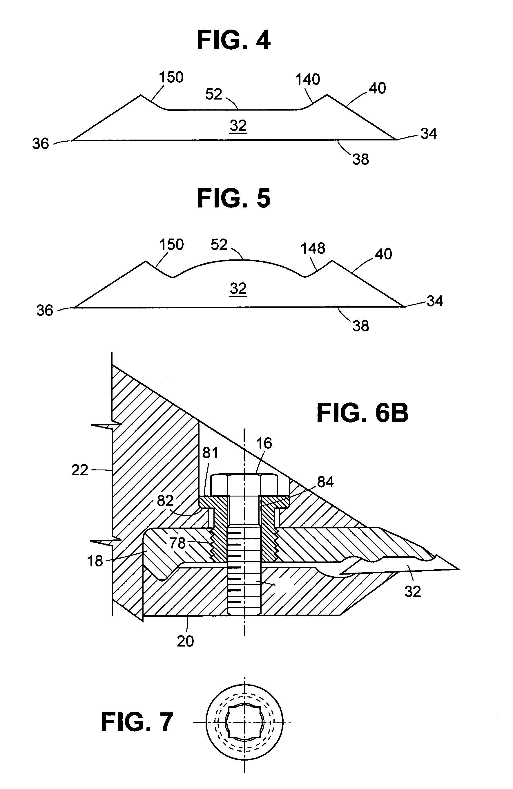
[0050]The clamping assembly 10 includes a fastener in the form of a bolt 12 having a shaft 14 and a head 16. A washer 13 abuts the head 16. The shaft 14 of the bolt 12 extends through a first clamping component which is preferably in the form of a rear clamping component 18 and a second clamping component which is preferably in the form of a front clamping component 20. The front clamping component 20 is secured to the base using a locking component which is in the form of a base bolt 17.

[0051]Although the bolt 12 is shown as the preferred fastener of th...


PUM

PropertyMeasurementUnit
clamping forcesaaaaaaaaaa
surface areaaaaaaaaaaa
shapeaaaaaaaaaa

Abstract

A wood working knife for use in a wood working machine, comprising a knife body having a first cutting edge and an opposed second cutting edge, the knife body having a first clamping surface and a second clamping surface. The first clamping surface has opposed clamping features separated by a middle section, the opposed clamping features and the middle section being sized and shaped such that, upon the knife body being inserted into a clamping assembly, the clamping forces are localized towards the opposed cutting edges and away from the middle section.

Description

FIELD OF THE INVENTION[0001]This invention relates generally to the forestry industry, and more specifically to the field of wood working machines of the type that are used to process wood to form chips or wafers for pulp or waferboard production, to form rough or finished lumber, or to form veneer for the production of plywood or laminated veneer lumber. Most particularly, this invention relates to wood working knives used in such machines, and to clamping assemblies to hold the knives in place.BACKGROUND OF THE INVENTION[0002]Wood is an important natural resource that is used in many of today's modern products. Within the forest industry, trees are harvested, cut into logs, and then subsequently undergo various processes to transform the logs into finished products. For example, in the pulp or oriented-strand board industries, the logs are passed through a machine which turns the solid log into chips or wafers. Such machines are typically referred to as chippers, which may be in a...

Claims


Application Information

Patent Timeline
Patent Type & Authority Patents(United States)
IPC IPC(8): B27C1/00B27G13/08B26D1/14B27G13/04B27G13/10B27L11/00
CPCB27G13/04B27G13/10B27L11/005Y10T407/1934Y10T407/1938Y10T407/192Y10T407/1924Y10T29/49963
Inventor BILLER, SVEN-OLOVGOUIN, MATHIEU J. A.LAGRANGE, DANIEL M.PLOUFFE, CHRISTIANZINNIGER, IAN G.
Owner IGGESUND TOOLS
Why Eureka
Try Eureka