
Pleated and cellular materials

a cellular material and pleat technology, applied in the field of window coverings, can solve the problems of limited transverse methods, limited patterns in the types of longitudinal methods, and tabs to wrinkles, and achieve the effect of uniform appearance and simplified handling

Inactive Publication Date: 2007-01-09
JUDKINS REN
View PDF13 Cites 53 Cited by
  • Summary
  • Abstract
  • Description
  • Claims
  • Application Information

AI Technical Summary

Benefits of technology

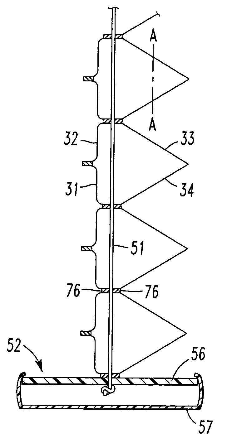
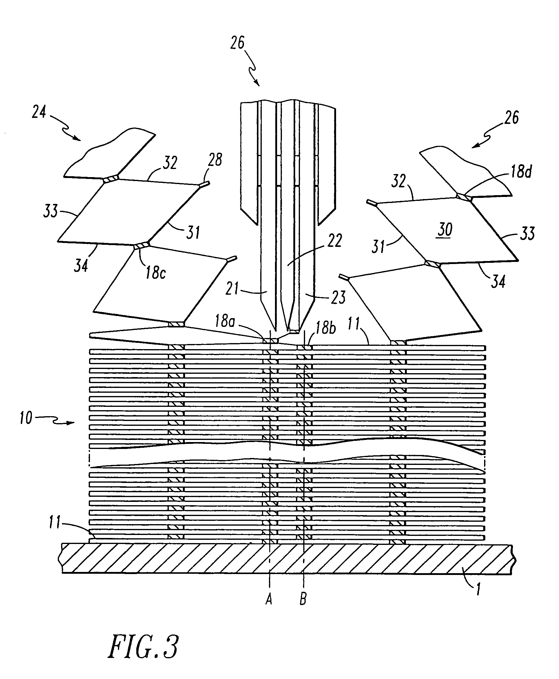
[0014]According to the teachings of the present invention, a stack of folded fabric is bonded to form a honeycomb structure having a series of cells connected together along bond lines. An interface region is present between adjacent cells which forms the bridge between horizontally adjacent stacks of cells. At least one bond line applied between adjacent fabric walls defines each interface region. These interface regions are split to form separate tabbed, pleated panels or separate panels of cells having tabs on one face between each pair of pleats. These tabs extending between each pleated panel or between individual cells, as the case may be, extend at least 1 / 16″ in length. To simplify handling and to create a uniform appearance the tabs are identical in size resulting from a straight-line split along a distinct perpendicular plane, but the invention is not limited to this.

Problems solved by technology

The longitudinal method is limited in the types of patterns that can be printed on the material because alignment is random.
The transverse methods have been limited to a single layer, a single tabbed layer or a triple layer where there are three continuous surfaces that create a panel of double cells.
This method tends to cause the tab to wrinkle because the stack is wrapped on a slightly curved mandrel.
Also, because the material layers are wound in a stack, the length of the panels of final product are limited to the height of the wrapped stack and the ends of the stack are wasted.

Method used


Image

  • Pleated and cellular materials
  • Pleated and cellular materials
  • Pleated and cellular materials

Examples


Embodiment Construction

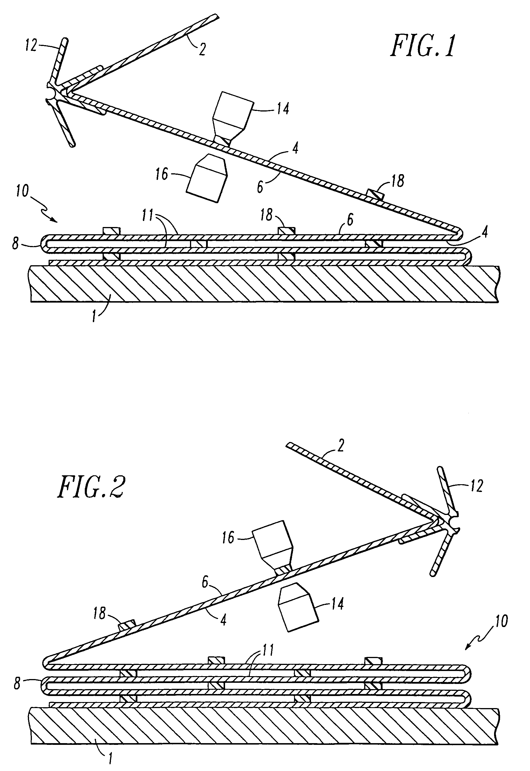
[0025]Referring to FIGS. 1 and 2, I provide a sheet of pleated fabric 2 which is folded on work surface 1 to form a fabric stack 10. Pleated fabric 2 is delivered to the work surface by a sprocket or other feed mechanism 12 which draws the fabric from a source of supply which is not shown. Glue applicators 14 and 16 apply bond lines 18 of hot melt glue on a surface 4 of the fabric. When the fabric is in the position shown in FIG. 1 surface 4 is facing upward. After the fabric has been laid from right to left across the length of stack 10, the fabric is folded as shown in FIG. 2. The movement of the stack relative to the fabric being supplied folds the fabric 2 back over the stack forming a pleat 8. Now surface 4 is facing down and opposite surface 6 is facing up. In that position glue applicator 16 applies lines of glue on surface 6. The fabric is laid across the stack from left to right. The process is repeated until a complete stack of fabric 10 has been created. That stack will t...


PUM

PropertyMeasurementUnit
lengthaaaaaaaaaa
temperatureaaaaaaaaaa
interior angleaaaaaaaaaa

Abstract

A tabbed honeycomb structure or pleated panel is made from a stack of collapsed multi-cellular material. The stack is split at bond lines thereby forming the panels of pleated or honeycomb material having a joint tab on one face. The tabbed, honeycomb material is attached between a headrail and a bottomrail to form a window covering.

Description

CROSS-REFERENCE TO RELATED APPLICATIONS[0001]This is a continuation in part of U.S. patent application Ser. No. 08 / 756,282 filed Nov. 25, 1996, which is a continuation of U.S. patent application Ser. No. 08 / 412,875, filed Mar. 29, 1995, and issued as U.S. Pat. No. 5,630,898 on May 20, 1997.BACKGROUND OF THE INVENTION[0002]1. Field of the Invention[0003]This invention relates to a tabbed and pleated cellular material and method for the manufacture thereof and more particularly to a window covering which contains this tabbed and pleated cellular material.[0004]2. Description of the Prior Art[0005]There are two basic types of folded window coverings. A first pleated type consists of a single layer of corrugated material. The other is a more complex cellular type where pleated layers are joined or folded strips are stacked to form a series of collapsible cells. This latter type is known to have favorable thermal insulation properties because of the static air mass which is trapped betwe...

Claims


Application Information

Patent Timeline
Patent Type & Authority Patents(United States)
IPC IPC(8): E06B3/48B31D1/00B31D3/02E06B9/262E06B9/266
CPCB26D1/09B31D1/0075B31D3/0215E06B9/262E06B9/266Y10T156/1052E06B2009/2627Y10T156/1003Y10T156/1015Y10T428/24149
Inventor JUDKINS, REN
Owner JUDKINS REN
Learn More