Vertical take-off and landing (VTOL) aircraft with distributed thrust and control

a technology of thrust control and vertical take-off, which is applied in the direction of vertical landing/take-off aircraft, aircraft navigation control, transportation and packaging, etc., can solve the problems of tilt rotor aircraft, the complexity of the mechanical linkage of the helicopter contributes significantly to the high cost and maintenance requirements of the craft, and the forward flight speed and efficiency of the conventional helicopter is significantly inferior to that of the conventional fixed-wing aircraft. achieve the effect of high-efficiency forward fligh

Inactive Publication Date: 2007-01-09
VANDERMEY TIMOTHY +1
View PDF20 Cites 155 Cited by
  • Summary
  • Abstract
  • Description
  • Claims
  • Application Information

AI Technical Summary

Benefits of technology

[0014]It is, therefore, an object of the present invention to provide a vertical take-off and landing (VTOL) propulsion system for aircraft that employs a distributed system of lifting propellers to achieve vertical take-off and landing as well as highly efficient forward flight.
[0015]It is another object to provide a VTOL aircraft that is highly reliable, safe, easy to fly, capable of taking off and landing vertically, hovering and transitioning to and from horizontal flight without the risk of stalling, and capable of flying horizontally with the forward flight speed and efficiency of a conventional fixed wing aircraft.

Problems solved by technology

However, because of its retreating blade and its basic construction the forward flight speed and efficiency of a conventional helicopter is significantly inferior to that of a conventional fixed wing aircraft.
Additionally, the complexity of the helicopter's mechanical linkages contributes significantly to the crafts high cost and demanding maintenance requirements.
However, tilt rotor aircraft have several distinctive drawbacks.
The first notable drawback is that tilt rotor aircraft must overcome negative angular moments created by tilting their spinning rotors 90 degrees during VTOL transitions.
These forces create inherently unstable conditions during the transitions between vertical and horizontal flight and visa versa.
In actual practice, this inherent instability has been largely responsible for a poor safety record for this type of aircraft.
A second drawback of the tilt rotor design is the fact that if the propulsion rotation system should fail the craft is rendered incapable of landing as a conventional fixed wing aircraft.
This limits their forward speed roughly to that of helicopters.
This craft has a high drag profile and is unsuited for high efficiency forward flight.
Since vertical and horizontal thrust are controlled by vectoring a common air stream the vertical thrust and horizontal thrust cannot be controlled independently.
This interdependence causes serious control and stability issues during VTOL transitions.
Secondly, since thrust is gained by vectoring high velocity air, the high velocity air stream will kick up any loose objects in its immediate proximity during take off and landing.
This phenomenon can pose a hazard to the aircraft and to ground personal.
Thirdly, since high velocity air is used to generate the lifting thrust, more power is required for vertical take off and landing than would be for an aircraft that generates its thrust over a larger area with a slower velocity air stream (i.e. a helicopter).
Because of this, not only must the aircraft power plant be capable of supplying the required additional power, but the large amount of fuel used during take off and land negatively affects the aircraft's effective range and flight time.
Fourthly, vectored thrust aircraft whose thrust jets are located in close proximity to one another do not provide a wide and stable “base” for the aircraft to balance on and are inherently unstable in hover.
As with the tilt rotor aircraft, the lack of aerodynamic lift and the negative angular moment caused by tilting the craft with its spinning rotors causes significant instability issues when transitioning between vertical and horizontal flight (and visa versa).
Additionally, for piloted aircraft, the tail setter provides the pilot with limited situational awareness during VTOL transitions and hover.
This type of aircraft typically suffers from several significant drawbacks.
First, if the craft has only a few small fans, high velocity air is required for sufficient thrust thus resulting in the hazards and inefficiencies previously noted for the vectored thrust aircraft.
If, however, the fan area is large the area taken by the fans will significantly impair the ability of the wing to develop lift during the transition time, when maximum lift is most needed.
This requirement for shuttering the fans during VTOL transitions adds further complexities and instabilities to the aircraft, particularly when transitioning from vertical to horizontal flight and visa-versa.
A second major drawback of the fan-in-wing aircraft is that the wings must be thicker than normal in order to house the ducted fans and their associated power transmission or power generation components.
The drag induced by the thicker wing geometry will limit forward flight speed and efficiency.
However, due to the large vertical openings and the wide fuselage body, the craft will have a large amount of induced drag and therefore is not suited for high efficiency forward flight.
Furthermore, the mechanical linkage complexities required to control the aircraft rival that of a helicopter, thus bringing with them the same maintenance and reliability issues found with the helicopter.
Since these non-winged craft derived the majority of their lifting force from vertical thrust, they are inherently inefficient in regards to forward flight when compared to a conventional fixed wing aircraft.
A major drawback of nearly all of the foregoing tilt rotor and tilt-duct designs is that the aircraft is unable to fly at all if one engine should fail.
Moreover, the complexity and costliness of such aircraft have been extreme.

Method used


Image

  • Vertical take-off and landing (VTOL) aircraft with distributed thrust and control
  • Vertical take-off and landing (VTOL) aircraft with distributed thrust and control
  • Vertical take-off and landing (VTOL) aircraft with distributed thrust and control

Examples


Embodiment Construction

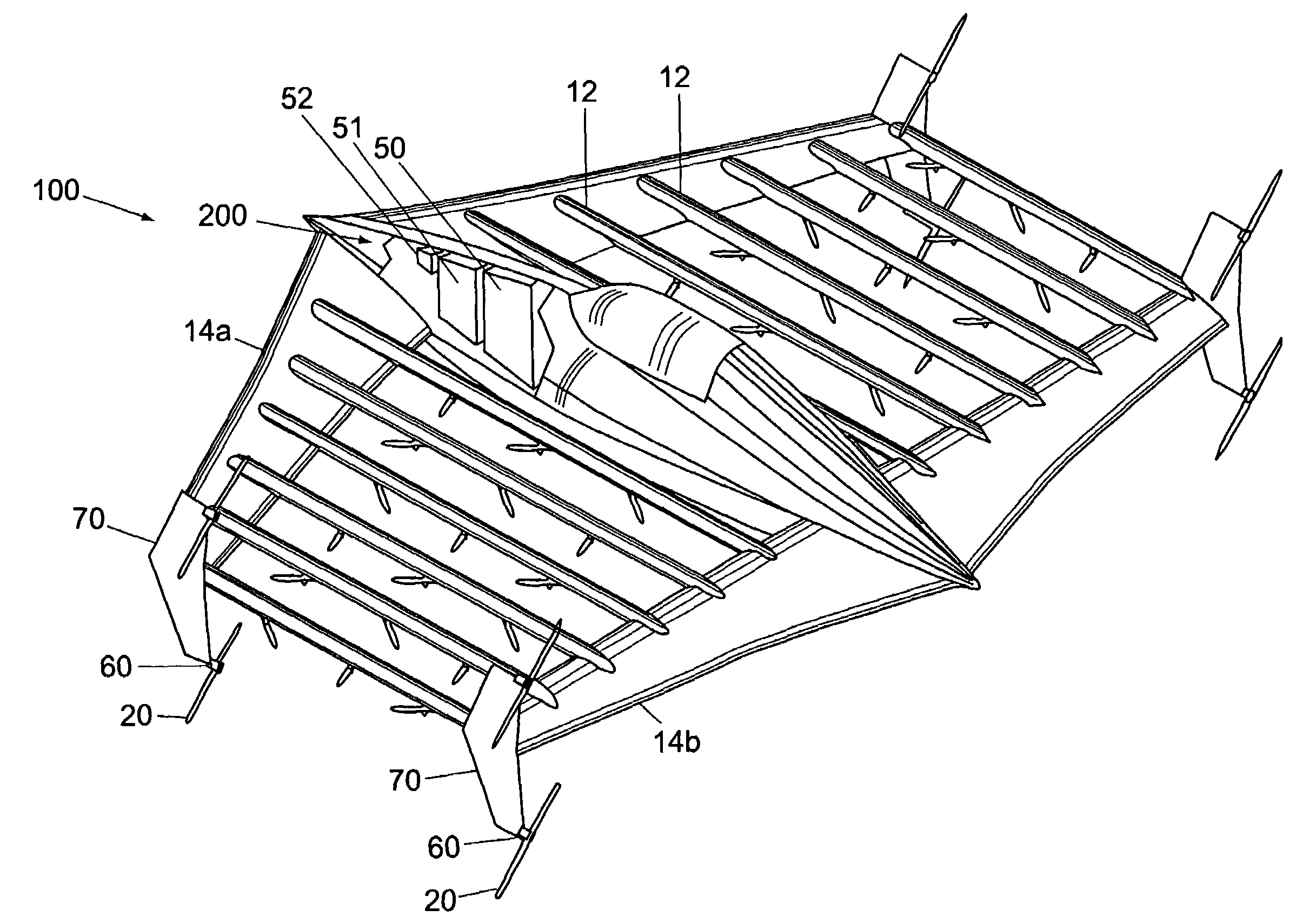
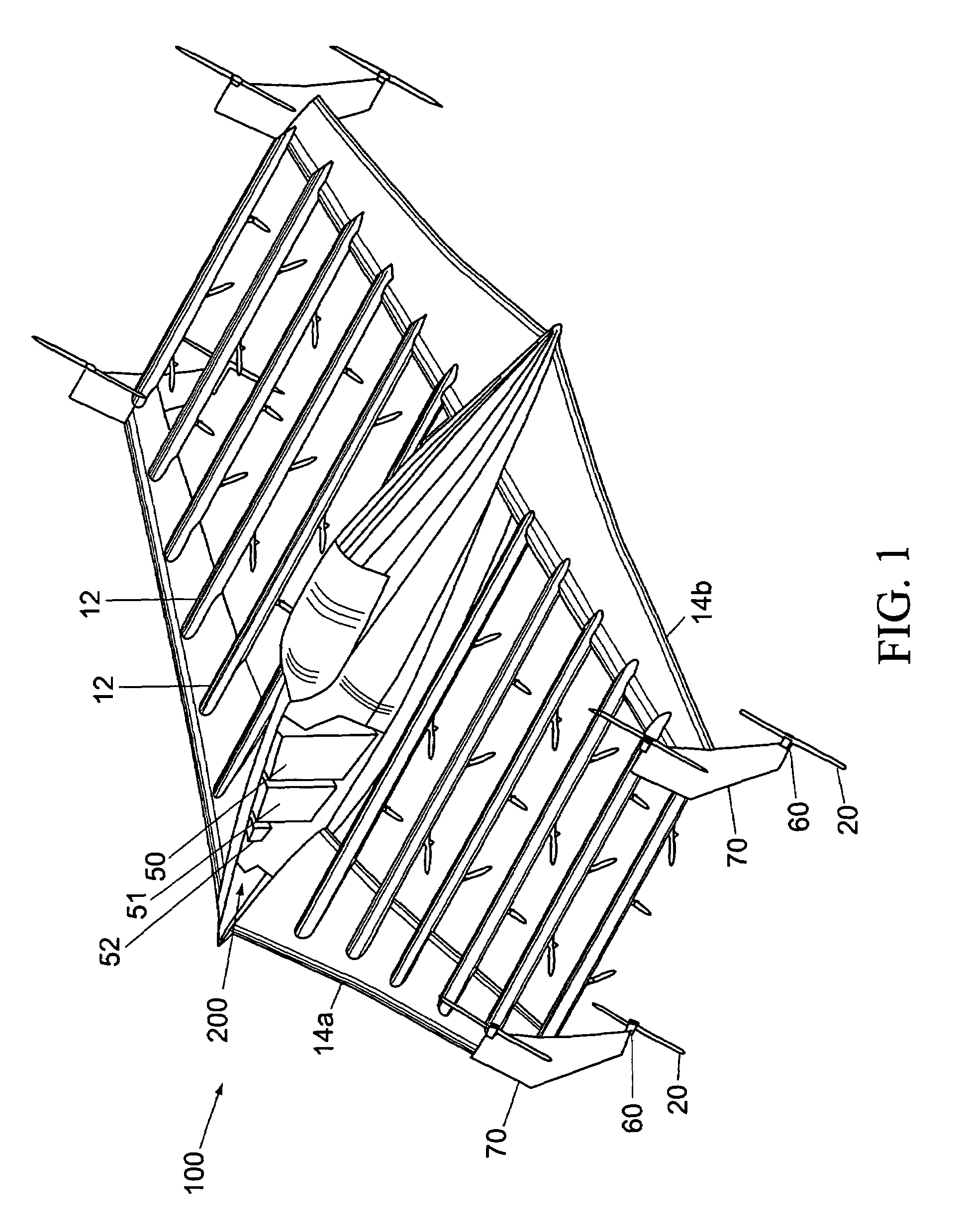
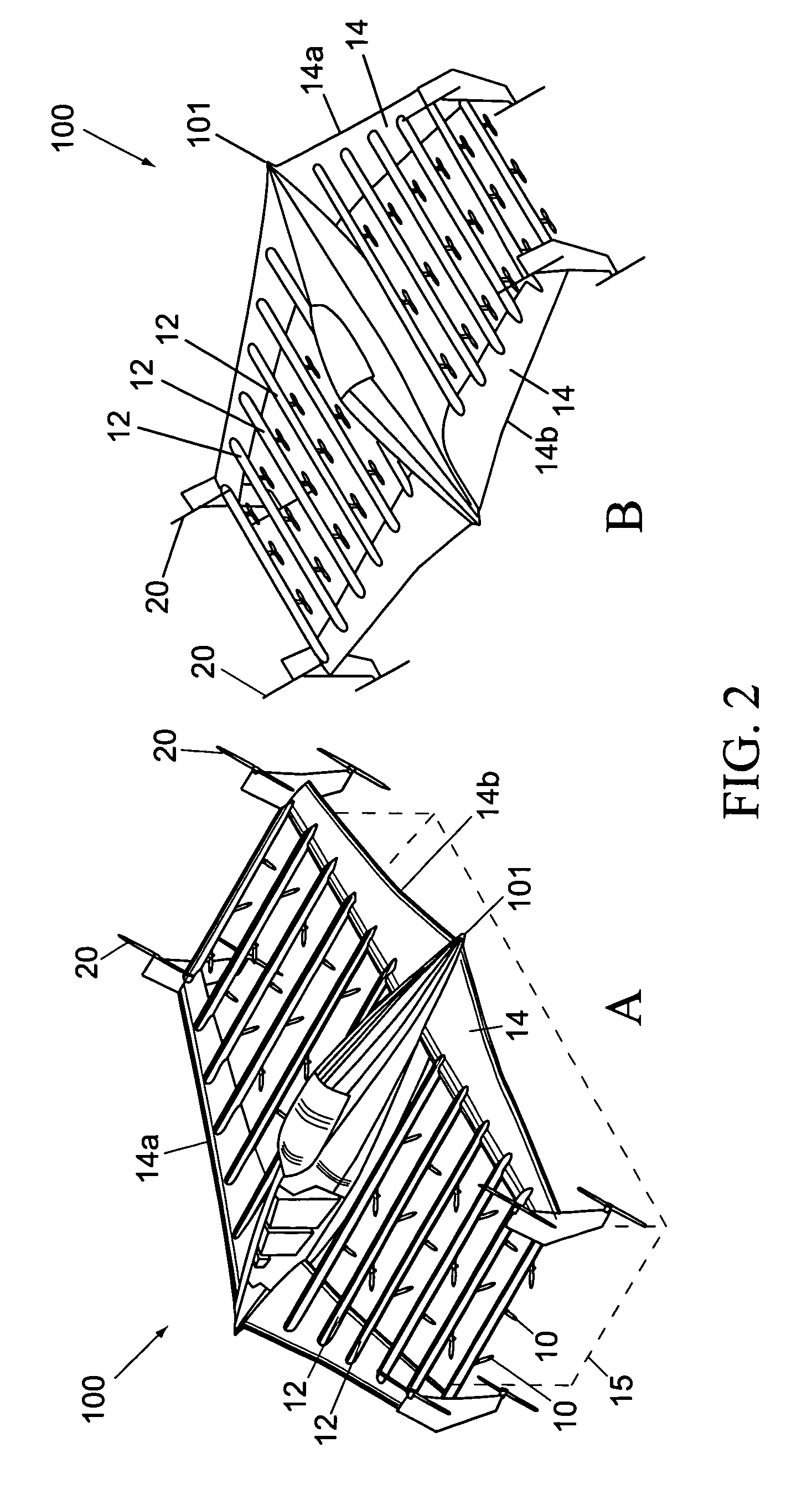
[0054]Referring in combination to FIGS. 1–5, the present invention is a vertical take off and landing (VTOL) aircraft 100 that is capable of highly efficient forward flight and incorporates a unique VTOL propulsion system.

[0055]FIG. 1 is a top view of an exemplary VTOL aircraft 100 with the unique VTOL propulsion system of the present invention incorporated therein. FIG. 2 is a composite illustration showing exemplary take-off (FIG. 2A) and in-flight (FIG. 2B) configurations of the VTOL aircraft 100 of FIG. 1.

[0056]The VTOL propulsion system of the present invention is incorporated into an aircraft 100 having fuselage 200 with wings 14a–b mounted fore and aft thereon. In the preferred embodiment, the fore wing 14a is swept and cambered to create lift during forward flight. Running fore to aft from wing 14a to 14b, (i.e. parallel to the fuselage 200), are a plurality of parallel spars 12. Generally, the VTOL propulsion system of the present invention includes a plurality of distribut...


PUM


Abstract

An aircraft having a vertical take-off and landing (VTOL) propulsion system. The aircraft includes a fuselage, the VTOL propulsion system, at least one forward thruster, a power source used for both the VTOL propulsion system and forward thruster, fore and aft wings and a plurality of spars attached to and spanning the space between the two wings. The VTOL propulsion system includes a plurality of VTOL cells (including a motor, motor controller, and propeller) attached in a spaced relation along each spar. The VTOL cells are used exclusively for vertical flight or hovering and are powered down as the aircraft develops forward flight velocity and corresponding wing lift. During forward flight the VTOL propellers are articulated to allow the aircraft to take on a low drag configuration. The present invention is suitable for use in manned or un-manned aircraft of any scale.

Description

BACKGROUND OF THE INVENTION[0001]1. Field of the Invention[0002]The present invention relates to aircraft propulsion systems and, more particularly, to a vertical take-off and landing (VTOL) propulsion system for aircraft that employs a distributed system of lifting propellers to achieve vertical take-off and landing as well as highly efficient forward flight.[0003]2. Description of the Background[0004]There are a variety of existing vertical take-off and landing (“VTOL”) aircraft in use today. For example, helicopters are VTOL aircraft. However, because of its retreating blade and its basic construction the forward flight speed and efficiency of a conventional helicopter is significantly inferior to that of a conventional fixed wing aircraft. Additionally, the complexity of the helicopter's mechanical linkages contributes significantly to the crafts high cost and demanding maintenance requirements.[0005]More recent efforts to improve the forward flight speed of vertical take-off an...

Claims


Application Information

Patent Timeline
Patent Type & Authority Patents(United States)
IPC IPC(8): B64C15/00B64C29/00
CPCB64C29/0016B64C39/08B64C39/068B64C39/062
Inventor VANDERMEY, TIMOTHYVANDERMEY, JOSIAH
Owner VANDERMEY TIMOTHY
Why Eureka
Try Eureka