Process and apparatus for molding polymer fittings

a technology of polymer fittings and molding processes, applied in the field of molding fluid flow components, can solve the problems of loss of yield, uneven polishing, and high unsuitability of conventional plastics and metallic tubing and plumbing components in these applications, and achieve the effects of improving fluid dynamics of fluid transport systems, reducing pressure drop, and increasing flow

Inactive Publication Date: 2007-01-09
ENTEGRIS INC
View PDF7 Cites 7 Cited by
  • Summary
  • Abstract
  • Description
  • Claims
  • Application Information

AI Technical Summary

Benefits of technology

[0009]In a preferred embodiment, an injection molded 90° sweep fitting improves fluid dynamics of fluid transport systems by reducing pressure drop, increasing flow, reducing dead volume, decreasing turbulence and maintaining even flow through the system. In addition, the invention includes a method and apparatus for manufacturing the fitting. The invention reduces shear rate of slurries, reduces dead volume, decreases turbulence and promotes even flow throughout the entirety of fab fluid flow systems.

Problems solved by technology

Conventional plastics and metallic tubing and plumbing components are highly unsuitable in these applications.
Uneven polishing creates unusable wafers and loss of yield.
The presence of the sharp inside corner can create a substantial pressure loss and consequently, a substantial decrease in flow rate as compared to flow through an equivalent sized straight tube.
Further, the sharp corners of a standard elbow create areas of turbulence and eddying.
Turbulence and eddy currents can cause particulate matter suspended in slurries to fall out of suspension and accumulate in areas of slow fluid flow.
Accumulated particulate matter may build up in these areas and slow the fluid flow through the conduit as well as create the possibility that lumps of particulate matter may break loose from the accumulation and be carried with the flowing fluid.
These lumps will destroy the uniformity of a polishing suspension and lead to expensive loss of yield in the wafer production process.
Sharp transitions also create increased friction between flowing fluid and the conduit.
Pressure drop within the system lowers flow rates and slows processing.
This produces the need for more powerful pumps and increases stresses on components in the portions of the system where pressures are higher increasing the risk of failure.
Turbulence also creates the possibility that cavitation will occur.
Cavitation tends to create increased wear on the surfaces of conduit walls shortening the life of components.

Method used


Image

  • Process and apparatus for molding polymer fittings
  • Process and apparatus for molding polymer fittings
  • Process and apparatus for molding polymer fittings

Examples


Embodiment Construction

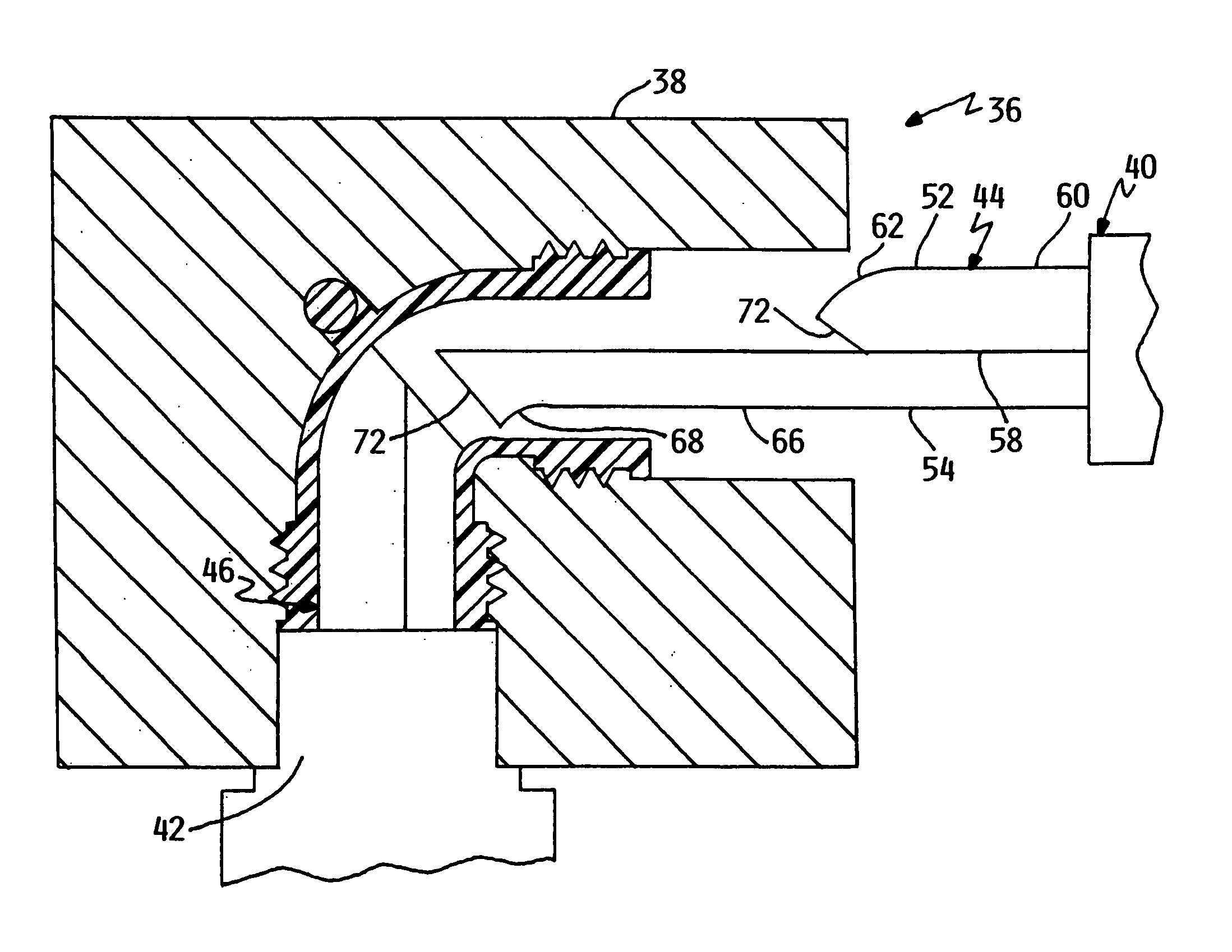
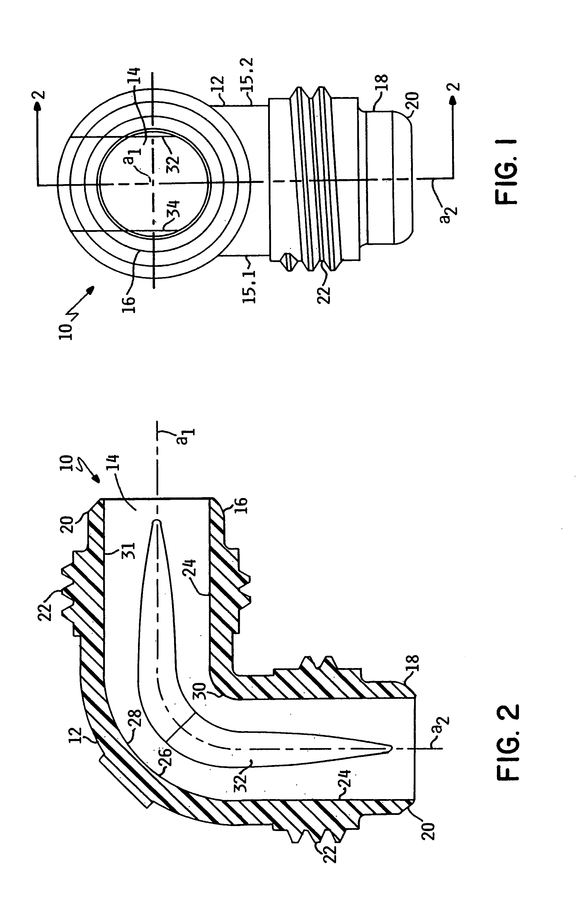
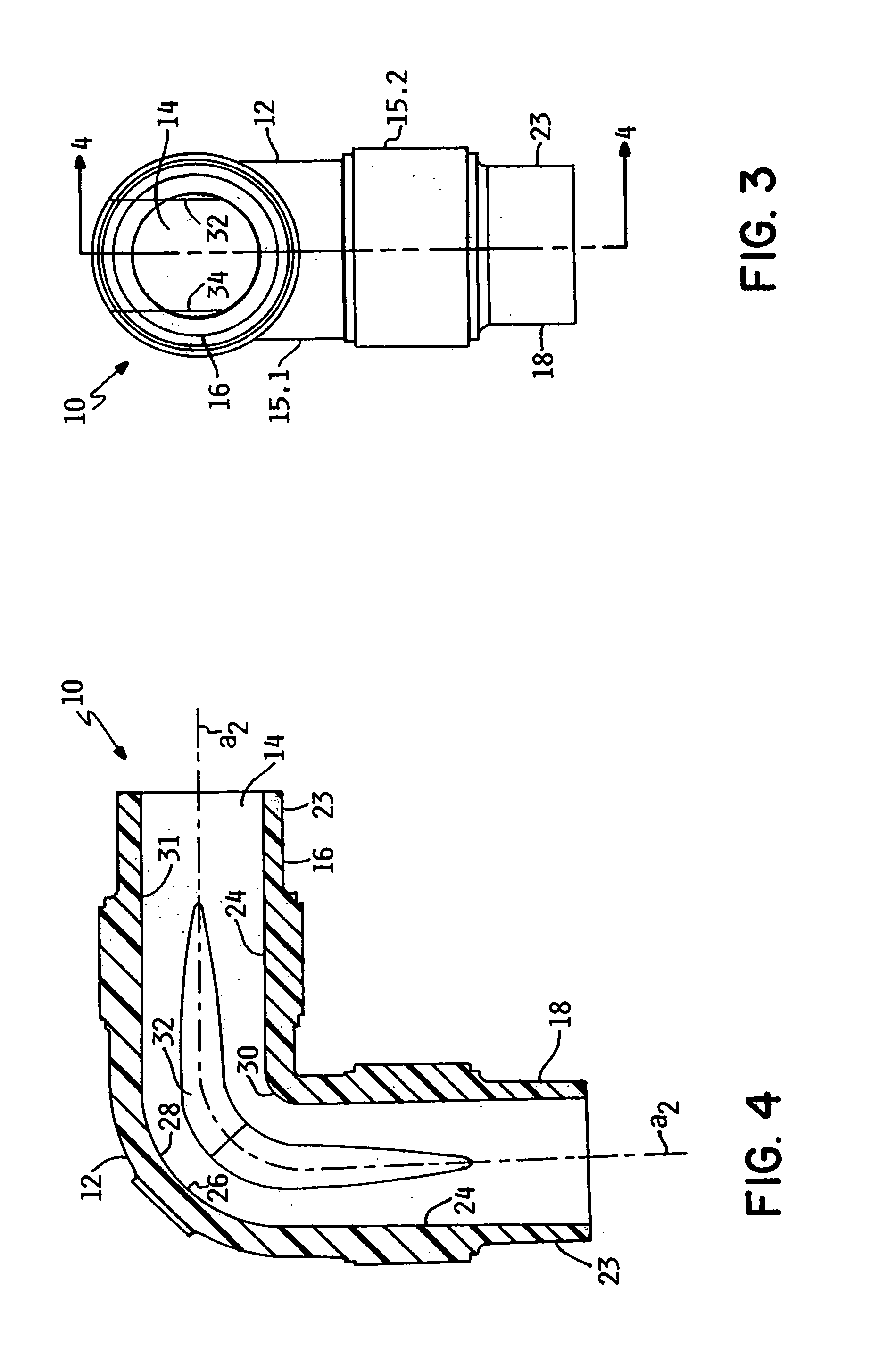
[0024]Referring to FIGS. 1–4, two exemplary embodiments of the invention are depicted. The components 10 in these examples are 90° sweep elbow fittings. They are formed of thermoplastics and in a preferred embodiment of fluoropolymers. The invention may be practiced with a variety of other fittings that have a sweep curve as part of their structure. Those skilled in the art will recognize that the invention may be applied to applications such as sweep elbows, sweep Ys, sweep Ts, sweep Us, traps and other fittings associated with valves, gages, flow meters, and other equipment apparatus used in fab plumbing installations utilizing fluoropolymer materials.

[0025]The component 10 has a body 12 enclosing a bore or lumen 14, with two sides 15.1, 15.2, defined and differentiated generally by the plane of the cross-sections in the figures, particularly FIGS. 1 and 3. The component 10, in this embodiment, generally includes a straight first end 16 and a straight second end 18 each with an ax...


PUM

PropertyMeasurementUnit
curvatureaaaaaaaaaa
linear refractionaaaaaaaaaa
corrosiveaaaaaaaaaa

Abstract

A method and apparatus for producing molded fluoropolymer sweep elbows with straight ends while minimizing distortion of the fitting. The invention includes a mold for creating the sweep fittings of the invention. The mold includes a mold cavity block and internal coring. The internal coring includes two symmetrical cores that shut off at a 45° miter. Each of the symmetrical cores is divided into two parts, an outside sweep core and an inside sweep core. The outside sweep core and the inside sweep core are divided on a straight plane running the length of the core. The outside sweep core molds half of the straight lumen and the greater curvature at the outside sweep surface of the bend. The inside sweep core molds the other half of the straight bore and the lesser curvature of the inside or undercut portion of the bend.

Description

RELATED APPLICATIONS[0001]This application claims the benefit of U.S. Provisional Patent Application Ser. No. 60 / 425,458 entitled “Process and Apparatus for Molding Polymer Fittings”, filed Nov. 12, 2002, hereby fully incorporated herein by reference.FIELD OF THE INVENTION[0002]The invention relates to the field of molding fluid flow components. More particularly, it relates to molding sweep polymer fittings while minimizing distortion of the fitting.BACKGROUND OF THE INVENTION[0003]In semiconductor manufacturing facilities, commonly known as fabs, highly corrosive, ultra pure liquids are utilized in manufacturing operations. Conventional plastics and metallic tubing and plumbing components are highly unsuitable in these applications. The materials of choice for plumbing components are fluoropolymer plastics such as PFA and PVDF because of their chemical inertness and non-wettability. The plumbing components will typically comprise tubing, valves, fittings, filters, sensors, tanks a...

Claims


Application Information

Patent Timeline
Patent Type & Authority Patents(United States)
IPC IPC(8): B29C33/34B29C45/00B29C45/26
CPCB29C33/485B29C45/2614Y10T29/49444B29L2031/243B29C45/36B29C45/00B29C45/40
Inventor KRANTZ, BRADLEYCADAVID, CARLOS A.NOWAK, DALE J.
Owner ENTEGRIS INC
Why Eureka
Try Eureka