Method and device for homogenizing glass melt

a technology of glass melt and homogenizing device, which is applied in the direction of glass making apparatus, manufacturing tools, transportation and packaging, etc., can solve the problems of uncontrollable geometric variation during hot finishing process, affecting optical depiction, and stirring coming into contact with the stirrer

Active Publication Date: 2013-01-08
SCHOTT AG
View PDF12 Cites 5 Cited by
  • Summary
  • Abstract
  • Description
  • Claims
  • Application Information

AI Technical Summary

Benefits of technology

The present invention provides a method and device for homogenizing glass melts by using a dynamic sealing of the marginal gap between the stirrer blades and the inside wall of the melt receptacle. This allows for a higher degree of homogeneity while applying low stress on the components of the device, enabling easy and precise adjustment and creating minimal abrasion or bubble shear rate. The invention also allows for a larger gap width between the stirrer blades and the inside wall of the melt receptacle, reducing interferences caused by high shear rates. The invention further prevents direct entry of the glass melt into the inner stirring region and actively or dynamically seals the gap between the wall region of the melt receptacle and the stirrer blades. The width of the marginal gap between the front ends of the stirrer blades and the inside surface of the melt receptacle or stirrer vessel is greater than approximately 5% to approximately 20%.

Problems solved by technology

Chemical inhomogeneities can result in inhomogeneities in the refractive index, which may impair optical depiction, for example, and in inhomogeneities in the viscosity, which may result, for example, in uncontrolled geometrical variations during hot finishing processes or hot processing.
An excessively narrow gap between the stirrer blades and the melt receptacle wall, however, poses the risk of the stirrer coming into contact with the wall of the melt receptacle, with consequent damage to the stirrer and / or the stirrer vessel.
Because thermally induced deformation of the stirrer or of the stirring system are unavoidable when heating to operating temperatures, the adjustment of the components is often no longer correct at the operating temperatures.
This can result in an excessively narrow distance between the stirrer blades and the melt receptacle wall, and thus in direct contact with the material, which ultimately results in destruction of the stirring system.
Due to the aforementioned thermal deformation of the components when heating the device to the operating temperature, the width of the gap cannot be consistently maintained, so that large marginal gaps must typically be specified.
For this reason, only unsatisfactory homogenization results are achieved with the state of the art, particularly for high-viscosity glass melts.
High shear stress between the stirrer blades and melt receptacle wall due to a narrow marginal gap can considerably impair the service life of the stirring system.
In addition, there is the risk that, if the stirring gap is excessively narrow, bubbles adhering to the melt receptacle wall may be sheared off and transferred into the product.
High shear stresses can also bring about abrasion of the wall material of the melt receptacle or stirrer vessel, resulting in micro-inclusions in the glass or the glass ceramic, which are not desirable, particularly in display glass products.
The dimensions of the stirring device produce a very narrow marginal gap, resulting in very high material stresses caused by the very high shear rates that are applied.
This results in a comparatively poor homogenization result.
A very narrow gap between the inside wall of the stirrer pot and the mixing blades is disclosed, which produces a very high mechanical load on the stirrer and the stirrer vessel.
A rotational speed increase, however, brings about an increased shear rate and thus a higher precious metal exposure level, including the undesirable generation of precious metal particles in the stirrer vessel.
An enlarged stirrer volume is associated with higher material use and costs.

Method used


Image

  • Method and device for homogenizing glass melt
  • Method and device for homogenizing glass melt
  • Method and device for homogenizing glass melt

Examples


Embodiment Construction

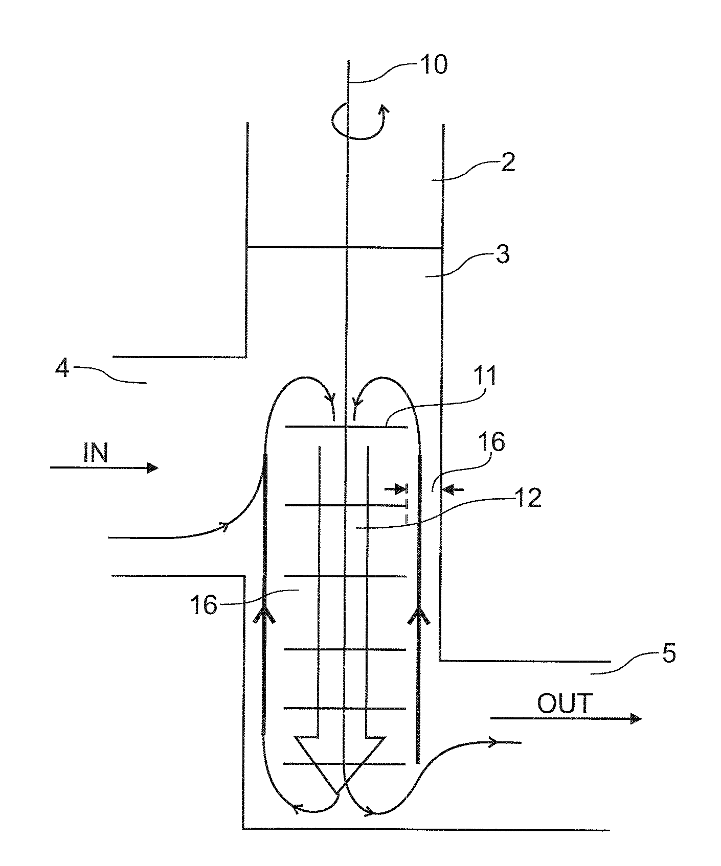
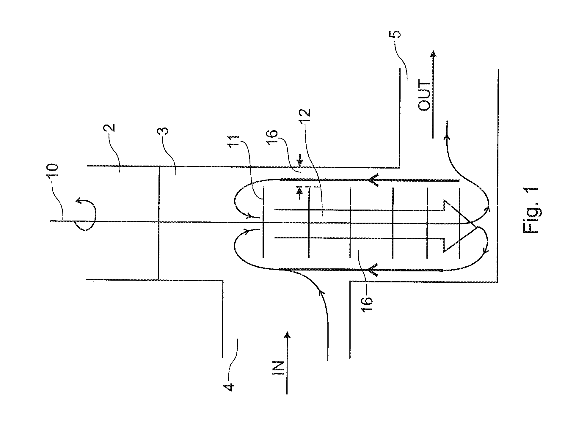
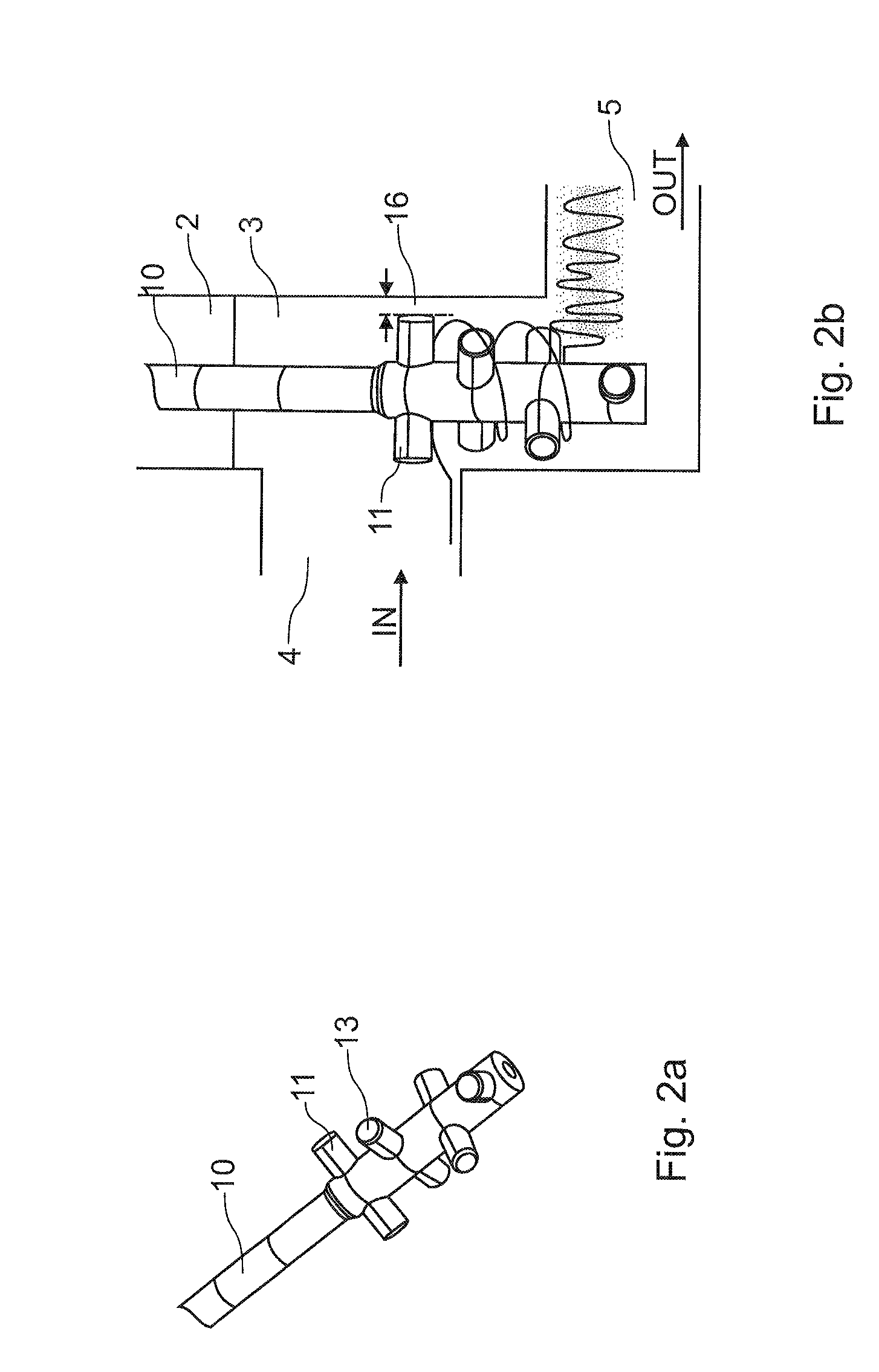
[0039]According to FIG. 1, a stirrer, which will be described hereinafter in more detail with reference to FIGS. 2a and 3a, comprising a plurality of stirrer blades 11 is disposed in a generally cylindrical stirrer vessel 2 in a point-symmetrical configuration. A glass melt 3 is received in the receptacle 2. The glass melt 3 can flow continuously or discontinuously through the stirrer vessel 2, specifically from the inlet 4 to the outlet 5. As is indicated by the arrow 12, an axial feed action is applied in the inner stirring region, between the stirrer shaft 10 and the front ends of the stirrer blades 11, which feeds the entering glass melt 3 from the upper axial end of the inner region 12 to the lower axial end thereof. This is achieved by suitably configuring the stirrer, which will be described in more detail hereinafter. The glass melt exiting at the lower axial end of the inner stirring region 12 brings about active sealing of the gap 16 between the front ends of the stirrer b...


PUM

PropertyMeasurementUnit
coverageaaaaaaaaaa
refractive indexaaaaaaaaaa
viscosityaaaaaaaaaa

Abstract

The invention relates to a device for homogenizing a glass melt in a melt receptacle, wherein at least one stirring device is disposed in a melt receptacle, which comprises a stirrer shaft and a plurality of stirrer blades, and wherein a gap (16) is formed between a wall region of the melt receptacle and the stirrer blades. According to the invention, the respective stirring device causes an axial feed action in an inner stirring region between the stirrer shaft and the stirrer blades in order to feed the melt in the stirring region along the stirrer shaft. A melt flow brought about by the axial feed action seals the gap against direct passage of the melt. According to the invention, a very high gap width can be achieved, thus preventing the abrasion of materials in the region of the marginal gap. This also reduces the complexity required for adjusting the device. According to the invention, a high level of homogenization can be achieved regardless of the entry point of the inhomogeneities.

Description

[0001]This is a divisional of U.S. patent application Ser. No. 11 / 957,727, which was filed on Dec. 17, 2007, under 35 U.S.C. 120. The aforesaid U.S. patent application claims the benefit of priority based on German Patent Application, DE 10 2006 060 9723, filed on Dec. 20, 2006 in Germany.FIELD OF THE INVENTION[0002]The present invention relates to the homogenizing of a glass melt, and particularly to the homogenizing of a glass melt used for the production of a glass or glass ceramic product having high quality and a low inclusions and / or imperfection density, such as display glass.BACKGROUND OF THE INVENTION[0003]The objective of homogenizing a glass melt is to reduce spatial and temporal variations in the chemical composition of the glass melt, in accordance with the product requirements. Chemical inhomogeneities can result in inhomogeneities in the refractive index, which may impair optical depiction, for example, and in inhomogeneities in the viscosity, which may result, for ex...

Claims


Application Information

Patent Timeline
Patent Type & Authority Patents(United States)
IPC IPC(8): C03B5/187
CPCB01F7/00125B01F7/00141B01F7/00258B01F7/00425C03B5/1875B01F7/00975B01F13/1016B01F13/1022B01F7/00908B01F13/1013Y02P40/57B01F27/0724B01F27/0722B01F27/1121B01F27/1144B01F27/50B01F27/2322B01F33/813B01F33/81B01F33/811C03B5/00C03B5/16C03B5/18C03B5/187
Inventor BERNDHAEUSER, CHRISTOPHLENTES, FRANK-THOMASNAUMANN, KARINDUEROLF, HANSHUNNIUS, HOLGER
Owner SCHOTT AG
Why Eureka
Try Eureka