
Implantable, miniaturized microbial fuel cell

a fuel cell, microorganism technology, applied in the direction of fuel cell details, cell components, electrochemical generators, etc., can solve the problems of incompatibility with implantable devices, lithium battery power sources tend to be relatively bulky and expensive, and microbial fuel cells of the prior art are typically too bulky

Inactive Publication Date: 2007-01-09
RGT UNIV OF CALIFORNIA
View PDF13 Cites 48 Cited by
  • Summary
  • Abstract
  • Description
  • Claims
  • Application Information

AI Technical Summary

Benefits of technology

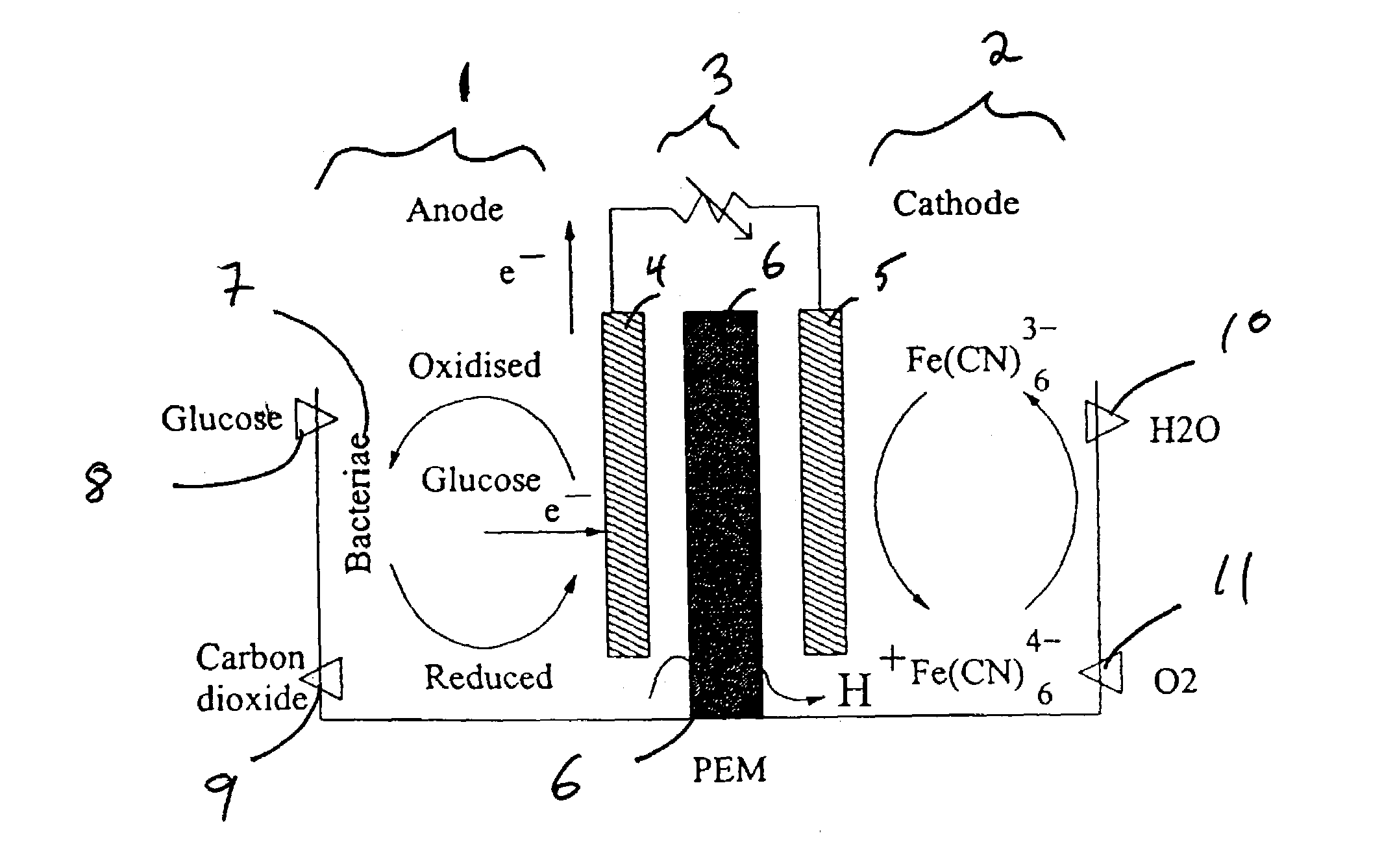
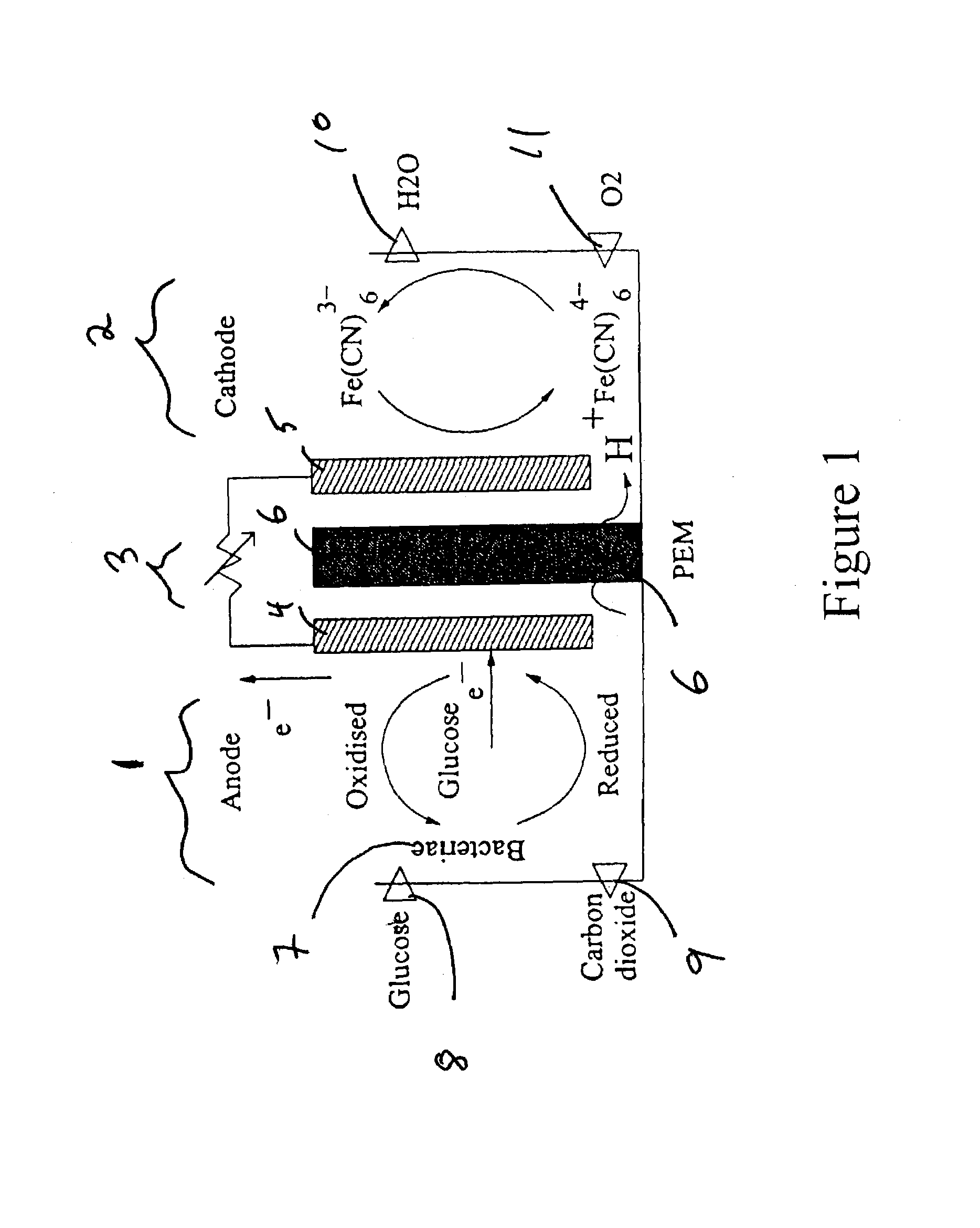
The invention is a small microbial fuel cell that uses the biological activity of microbes, such as baker's yeast, to generate electricity. It requires only glucose and oxygen as fuel and produces only carbon dioxide and water as waste. The cell can be used as a power source for implantable biomedical devices, such as sensors and stimulators. The technology used to make the cell is called MEMS, which allows for the integration of the fuel cell with other biomedical devices, reducing their size and cost. The fuel cell is also a renewable, long-term power source for implantable devices as it extracts glucose or other metabolites from the body's fluids.

Problems solved by technology

However, lithium battery power sources tend to be relatively bulky and expensive.
Conversely, the microbial fuel cells of the prior art are typically too bulky, chemically and / or biologically incompatible for use in conjunction with implantable devices.

Method used


Image

  • Implantable, miniaturized microbial fuel cell
  • Implantable, miniaturized microbial fuel cell
  • Implantable, miniaturized microbial fuel cell

Examples


example 1

[0060]The open circuit voltage response as a function of time of the above microbial fuel cell (FC-I) is depicted in FIG. 5. In both cases depicted in FIG. 5, methylene blue was used as an electron mediator in the anode compartment. For anolyte solution including yeast (solid triangles), the open circuit voltage fluctuates from about 160 millivolts (mV) to about 480 mV with an average voltage over the 43 minute test period of approximately 343 mV. For anolyte without yeast (open squares), but otherwise having the same composition as the solid triangles, the voltage is seen to remain at a substantially constant 25 mV.

example 2

[0061]The effect of methylene blue electron mediator on fuel cell performance is considered. Anolyte without methylene blue (but including yeast) is introduced into the anode compartment. The open circuit potential is found to increase from about 25 mV to about 40 mV in about 10 minutes, and then to remain at about 40 mV for approximately 30 minutes more. When fresh anolyte is added into the fuel cell's anode compartment along with the anolyte already present, a time delay of approximately 10 min to 15 min is observed before the open circuit potential reaches its peak value.

[0062]The ramping rate of the open circuit potential seen in FIG. 5 may be largely determined and limited by the rate of yeast metabolism and could be improved if a more metabolically active microbe were used.

[0063]The decline in open circuit potential observed to occur in FIG. 5 after about 30 minutes is likely due to the consumption of available glucose and the consequent decline in the rate of production of el...

example 3

[0064]Fuel cell discharge tests were also performed under 10 ohm and 50 ohm loads and results are given in FIG. 6. Under a 50 ohm load, the current initially jumped to approximately 1.3 μA / cm2 (microamps / sq. cm.) after the first few drops of anolyte and catholyte were introduced into the anode and cathode respectively. The current density under 50 ohm load dropped to approximately 0.58 μA / cm2 after about 5 minutes. However, it is consistently observed that the current density recovers to about 1.2 μA / cm2 after fresh drops of anolyte and catholyte are introduced into the fuel cell. Under a 10 ohm load, the current density initially rises to approximately 15 μA / cm2 then drops to approximately 3.6 μA / cm2 after about 14 minutes. The power density of the fuel cell (I2R) is approximately 0.5 microwatt per cm3 under a 10 ohm load.

Fuel Cell Structure II (FC-II)

[0065]FIG. 11 depicts in cross-sectional view the anode-PEM-cathode assembly typically used in some embodiments of the present inven...


PUM

PropertyMeasurementUnit
diameteraaaaaaaaaa
surface area-to-volume ratiosaaaaaaaaaa
thicknessaaaaaaaaaa

Abstract

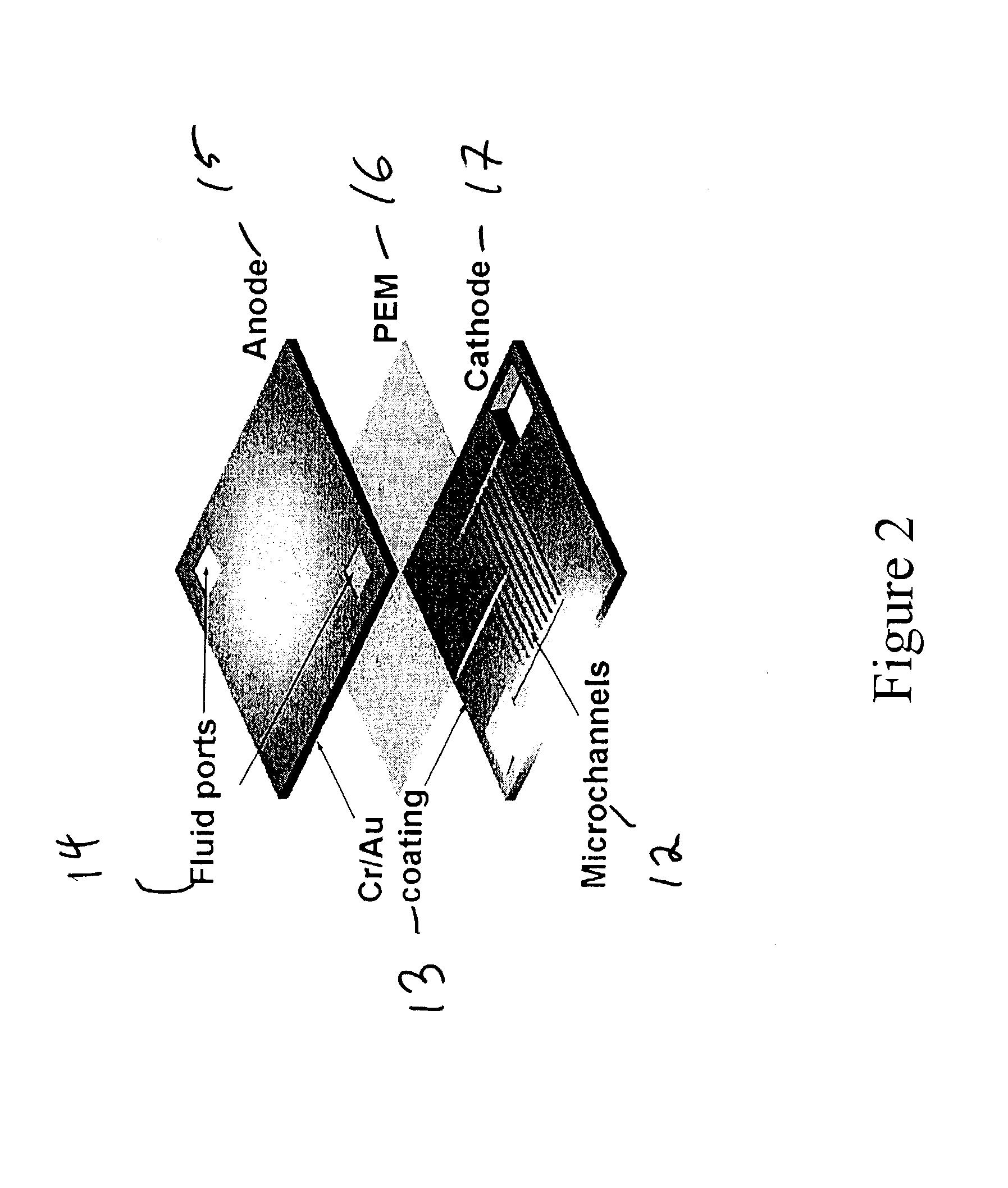
A miniaturized microbial fuel cell is described deriving electrical power from the biological activity of microbes, typically the metabolism of glucose by baker's yeast. Microfabrication techniques are used to miniaturize the components as well as the overall fuel cell and are capable of integration with other biomedical and implantable devices. Substantial reductions in both the size and the cost of implantable systems are thereby achievable. Electrode structures are used that facilitate electron transfer and power production giving favorable power densities in a miniature fuel cell. In addition, the microbial fuel cell of the present invention extracts glucose or other metabolite(s) from the ambient body fluids as its fuel, thus achieving a renewable, long-term power source for implantable biomedical devices.

Description

STATEMENT REGARDING FEDERALLY SPONSORED RESEARCH OR DEVELOPMENT[0001]This invention was made with Government support under Grant (contract) No. F30602-00-2-0566 awarded by DARPA. The Government has certain rights to this invention.BACKGROUND OF THE INVENTION[0002]1. Field of Invention[0003]This invention relates generally to the field of microbial fuel cells and, more particularly, to miniaturized microbial fuel cells suitable for bioimplantation as well as to components and microfabrication techniques related thereto.[0004]2. Description of the Prior Art[0005]The use of biochemical activity of microorganisms to generate electricity has been studied by several groups of investigators. See, for example, the work of Kim et al (U.S. Pat. No. 5,976,719), Zeikus et al (U.S. Pat. Nos. 6,270,649 and 6,495,023) and references cited therein. Indeed, microbial electrochemistry and the generation of electrical power by means of a microbial fuel cell is sufficiently well developed to have becom...

Claims


Application Information

Patent Timeline
Patent Type & Authority Patents(United States)
IPC IPC(8): H01M8/10H01M8/16H01M4/86H01M4/88H01M8/02
CPCH01M8/0206H01M8/0215H01M8/16H01M8/0228Y02E60/527Y02E60/50
Inventor CHIAO, MULIN, LIWEILAM, KIEN-BANG
Owner RGT UNIV OF CALIFORNIA
Learn More