Motor drive apparatus, electric actuator and electric power steering apparatus

a technology of motor drive and actuator, which is applied in the direction of electric generator control, dynamo-electric converter control, dynamo-electric gear control, etc., can solve the problems of discontinuous control, reduced control stability, and fluctuation in torque, and achieve high torque area and drive speed. high

Active Publication Date: 2007-01-09
HITACHI ASTEMO LTD
View PDF19 Cites 94 Cited by
  • Summary
  • Abstract
  • Description
  • Claims
  • Application Information

AI Technical Summary

Benefits of technology

[0011]Another object of the present invention is to provide a motor drive apparatus, electric actuator and electric power steering apparatus capable of continuous torque control up to the high drive speed and high torque area, without any failure even when a detection error has occurred to the current sensor.[MEANS FOR SOLVING THE PROBLEMS]
[0034]This structure ensures continuous torque control up to the high drive speed and high torque area, without any failure even when a detection error has occurred to the current sensor.
[0047]The present invention ensures continuous torque control up to the high drive speed and high torque area, without any failure even when a detection error has occurred to the current sensor.

Problems solved by technology

Accordingly, the following problems occur: (1) A fluctuation in torque occurs at the time of switching.
(3) Discontinuous control at the time of switching and reduced control stability.
Further, in the actuator capable of quick acceleration and deceleration up to the high torque range, a hunting problem tends to occur to the switching processing section, with the result that smooth torque control cannot be obtained, according to the prior art.
If an error has occurred to the detection value of these multiple current sensors, torque control fail.
This requires the motor drive to be suspended (failed).
Thus, the motor drive cannot be continued.
Such a problem has been found in the prior art.

Method used


Image

  • Motor drive apparatus, electric actuator and electric power steering apparatus
  • Motor drive apparatus, electric actuator and electric power steering apparatus
  • Motor drive apparatus, electric actuator and electric power steering apparatus

Examples


Embodiment Construction

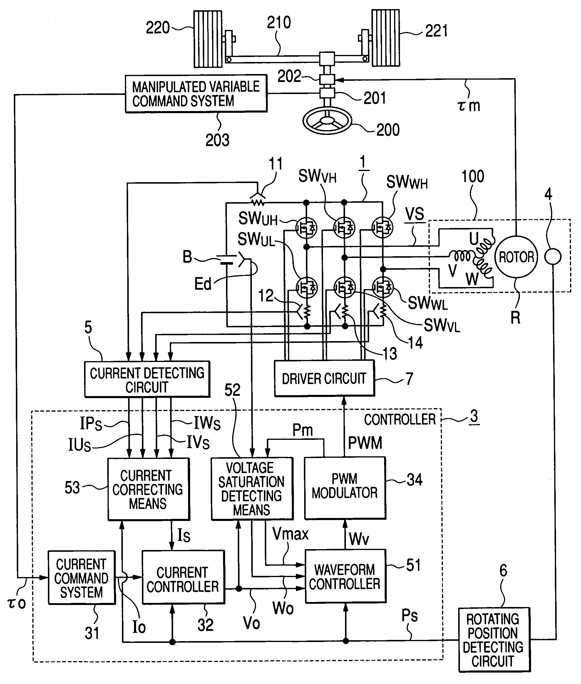
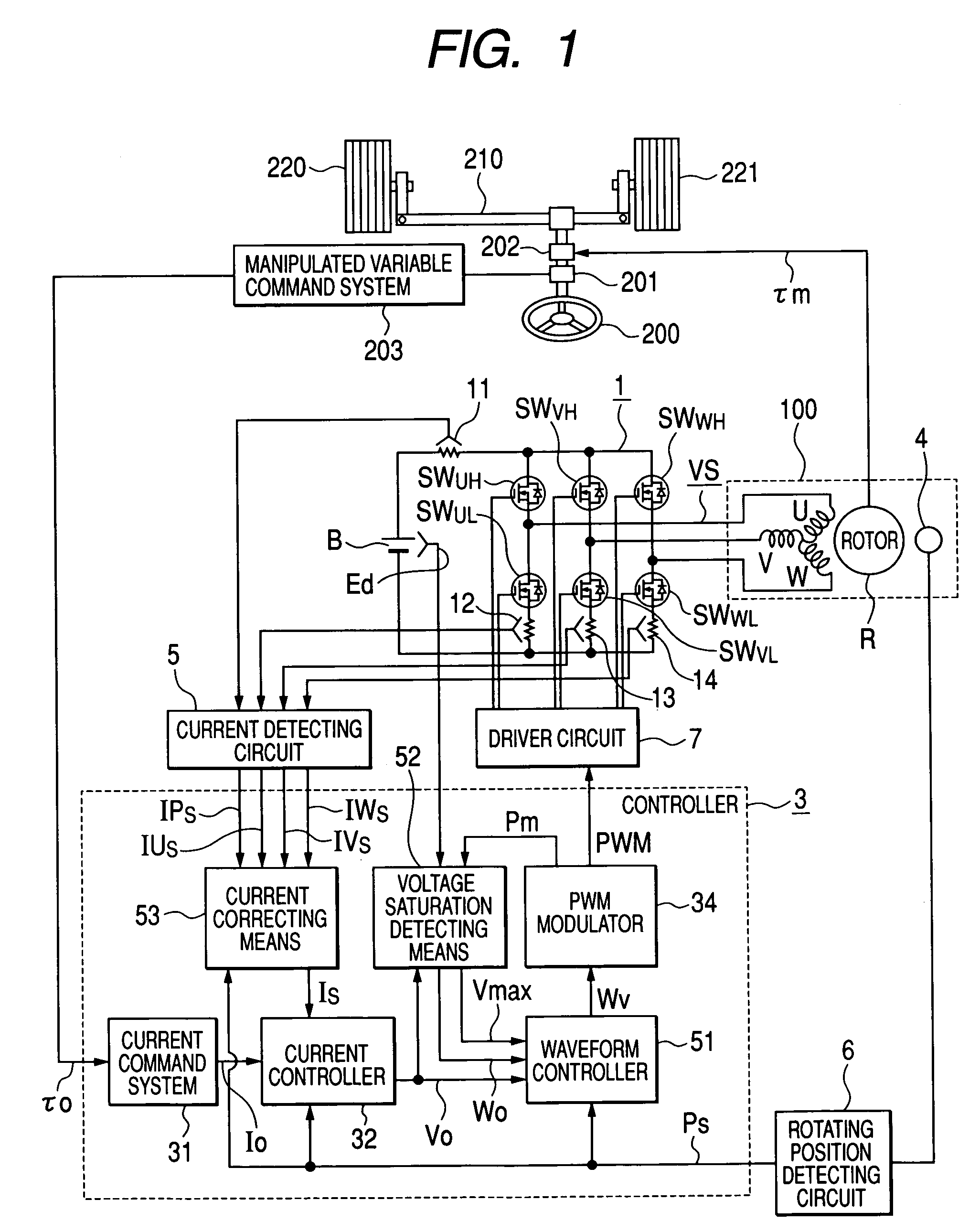
[0059]Referring to the drawings 1 through 7, the following describes the configuration and the operation of a motor drive apparatus as an embodiment of the present invention: The following description refers to an example of the electric power steering apparatus wherein the motor drive apparatus of the present embodiment is used as an electric actuator. In addition to the permanent magnet synchronous motor (brushless d.c. motor), any other motor that can be a.c. driven, permanent magnet synchronous motor, can be used as the a.c. driven motor, without the present invention being restricted to the following example. Further, it is also applicable to the electric braking apparatus wherein the motor drive apparatus is used as an electric actuator.

[0060]In the first place, the following describes the configuration of the electric power steering apparatus wherein the motor drive apparatus of the present embodiment is used as an electric actuator, with reference to FIG. 1:

[0061]FIG. 1 is a...


PUM


Abstract

The disclosure concerns a a motor drive apparatus, an electric actuator and an electric power steering apparatus capable of continuous torque control up to the high drive speed and high torque area, in order to enable quick acceleration and deceleration. A controller comprises a voltage saturation detecting apparatus for detecting the voltage saturation of the output voltage of an inverter circuit, based on the battery voltage, and a waveform controller that converts the drive waveform of the inverter circuit into the waveform created by superimposing harmonics of high odd-numbered order on a sinusoidal wave as a fundamental wave of the modulated wave modulated by a PWN carrier wave; and continuously changes the ratio of superimposing the high-order harmonics in response to the voltage saturation detected by a voltage saturation detecting means. This arrangement allows the controller to continuously change the drive waveform of the inverter circuit.

Description

CLAIM OF PRIORITY[0001]The present application claims priority from Japanese application serial no. 2004-192751, filed on Jun. 30, 2004, the content of which is hereby incorporated by reference into this application.FIELD OF THE INVENTION[0002]The present invention relates to a motor drive apparatus, an electric actuator and an electric power steering apparatus, particularly to the motor drive apparatus, electric actuator and electric power steering apparatus that are preferably used for quick acceleration and deceleration.BACKGROUND OF THE INVENTION[0003]In recent years, a power steering apparatus has been developed wherein the steering force of a driver is mitigated under motor control by detecting the steering force of a vehicle. Attention is currently focused on a brushless motor used in this power steering apparatus. The brushless motor has a rotor equipped with a permanent magnet. It drives the inverter circuit in response to the signal of detecting the rotational position as ...

Claims


Application Information

Patent Timeline
Patent Type & Authority Patents(United States)
IPC IPC(8): H02J1/02H02P27/00B62D5/04H02P6/06H02P6/08H02P6/28H02P21/00H02P21/05H02P21/22H02P23/04H02P23/07H02P27/04H02P27/08
CPCB62D5/046B62D5/0463F16D65/18H02P6/10H02M2001/0009H02P2209/07F16D2121/24H02M1/0009
Inventor AJIMA, TOSHIYUKIMIYAZAKI, HIDEKIKANEKO, SATORUTAKAMUNE, YUUICHIROU
Owner HITACHI ASTEMO LTD
Why Eureka
Try Eureka