
System for arraying surface mount grid array contact pads to optimize trace escape routing for a printed circuit board

Active Publication Date: 2007-01-09
NVIDIA CORP
View PDF2 Cites 18 Cited by
  • Summary
  • Abstract
  • Description
  • Claims
  • Application Information

AI Technical Summary

Benefits of technology

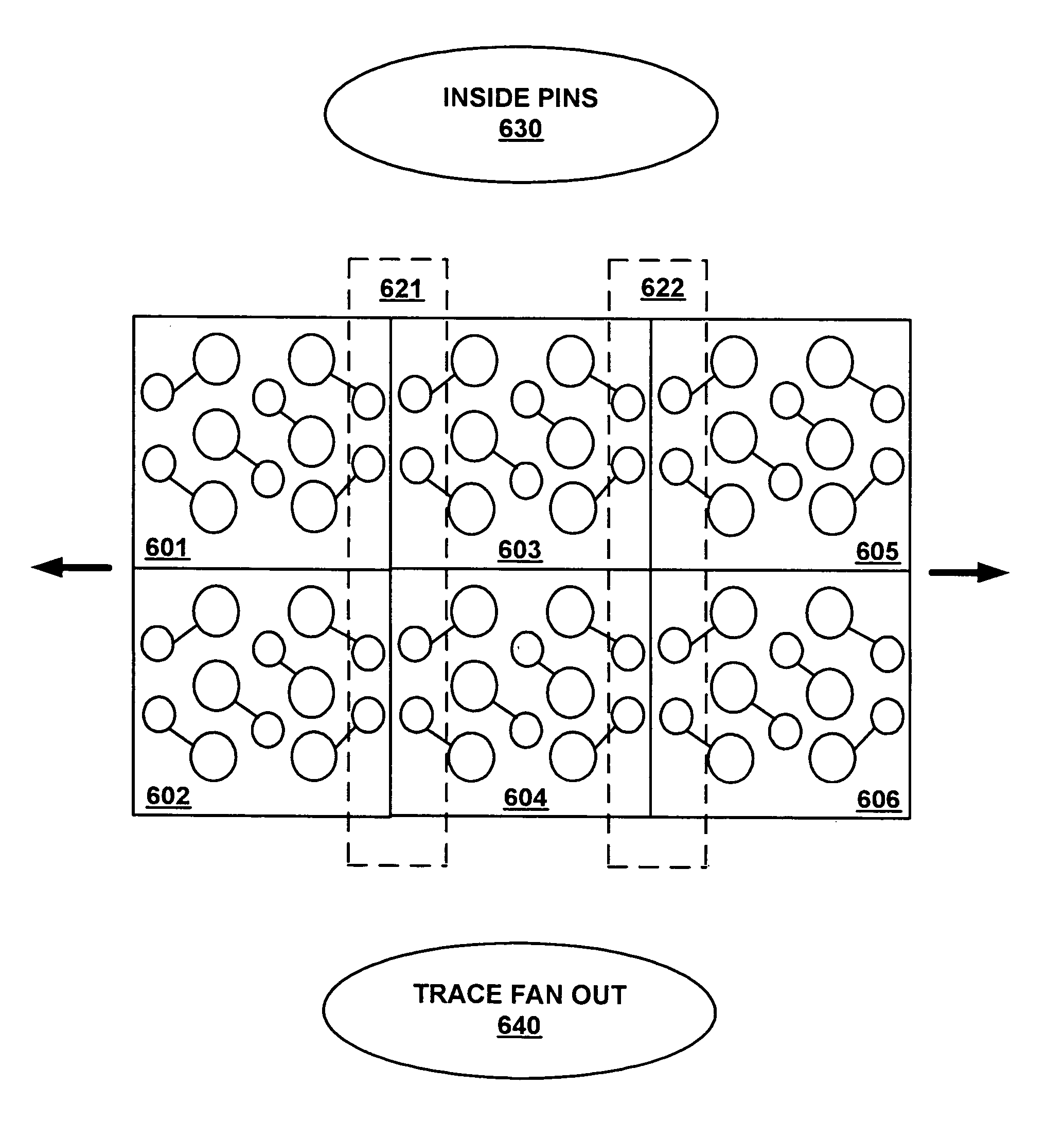
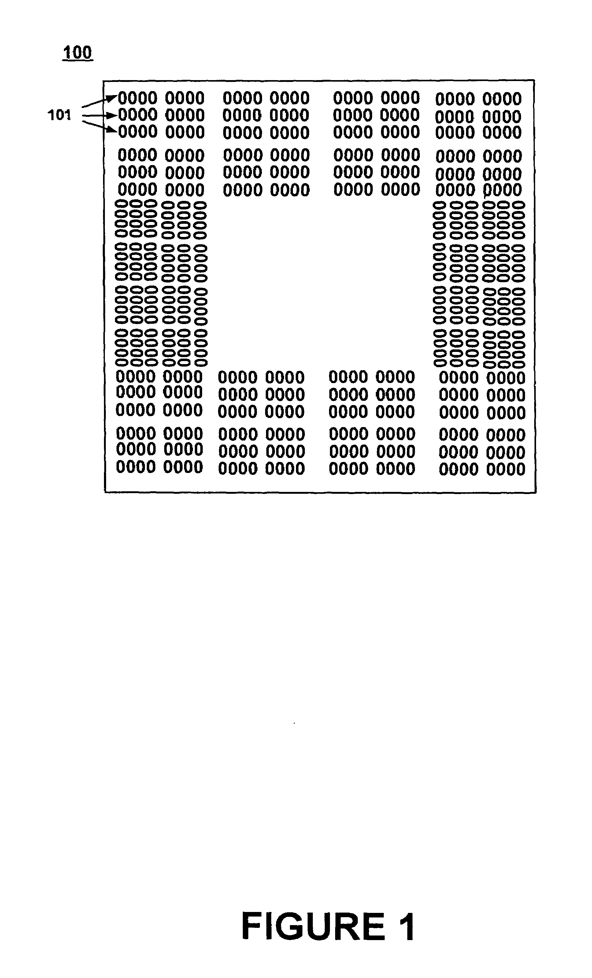
[0014]Embodiments of the present invention provide a system for arraying any surface mount grid array of contact pads and their connecting vias to optimize trace escape routing in the printed circuit board (PCB). Embodiments of the present invention can reduce the number of PCB layers required to implement interconnections for complex integrated circuit components. Embodiments of the present invention minimize the impact of vias between layers of the PCB on the trace routing of the PCB. Additionally, embodiments of the present invention are capable of functioning with conventional design rules and via construction technology for the fabrication of PCBs.
[0018]In this manner, the trace escape channels minimize the impact of the vias on the trace escape routing of the PCB, thereby allowing a trace escape routing pattern from an integrated circuit device to be implemented with fewer PCB layers in comparison to the prior art. The reduction in the number of PCB layers required leads to a corresponding reduction in the cost of the resulting PCB, and a corresponding increase in the reliability of the resulting PCB. Additionally, the use of trace escape channels provide an added degree of trace escape route ability, thereby allowing the use of conventional design rules and via construction technology for the fabrication of PCBs, and eliminating any requirement for exotic or overly expensive PCB fabrication technology.
[0019]The present invention also improves the arrangement of via holes in the copper planes, in the direction of current flow. In one embodiment, such an arrangement of via holes in the direction of current flow yields 5 times the amount of copper for DC or AC transient power supply and for high-speed signal return paths.

Problems solved by technology

As the complexity of integrated circuit technology has increased, the sophistication and complexity of PCB technology has also increased.
A problem exists however, in the use of multilayer PCBs.
Since each layer is fabricated using a separate etching process, each added layer adds to the expense of the overall PCB.
Additionally, since each layer must be glued or otherwise combined with the other layers, the process of combining the layers adds to the expense and also increases the chances of introducing flaws into the finished PCB.
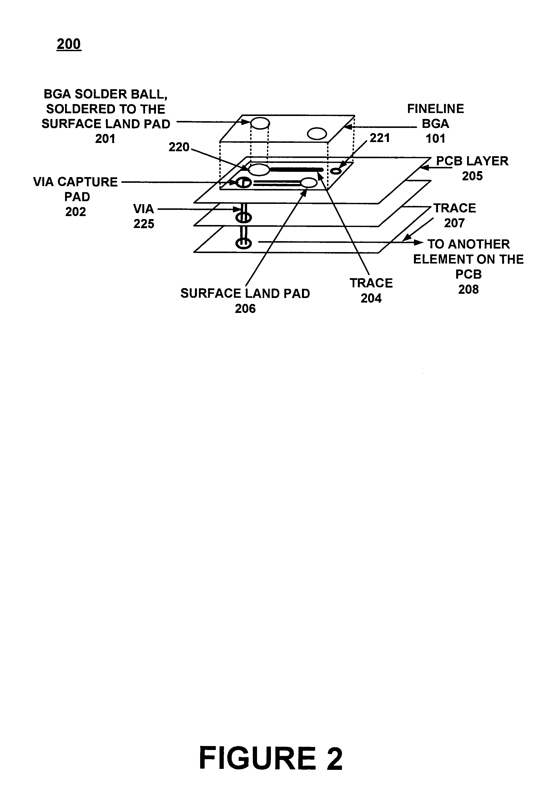
Another problem exists in the fact that interconnections between the layers of a PCB are implemented using “vias” which penetrate the trace conductor patterns of one layer to form a connection with the trace conductor patterns of another layer.
Such vias waste space that could otherwise be used to route other signal traces.
This can be particularly problematic in the case of a complex integrated circuit component having several hundred signal traces which must be routed.
The traditional disposition of vias across a PCB is a dominant obstruction that can consume PCB real estate for trace routing.
The placement of vias is ‘expensive’ in terms of trace routing since it consumes space that would otherwise be used for routing 4, 5, or even 6 traces.
This problem exists for each layer of the PCB through which vias must be implemented.
A designer's ability to cope with this problem is limited by conventional PCB fabrication design rules and via construction technology (e.g., which allocates a standard spacing per via, etc.).
Because of these reasons, conventional prior art routing limitations dictate that vias are regularly placed at the same pitch as their connecting ball.
In addition to the problem of stifling the space to route the signal traces out from a surface mount array (typically of pins, but also any form of surface mount connection) to surrounding devices, the vias also have a severe impact on the layers in the PCB construction that are used to deliver the power into the IC.
The degradation of this copper plane caused by holes around the vias, limits how much power can be delivered and how fast the high-speed signals can transition.

Method used


Image

  • System for arraying surface mount grid array contact pads to optimize trace escape routing for a printed circuit board
  • System for arraying surface mount grid array contact pads to optimize trace escape routing for a printed circuit board
  • System for arraying surface mount grid array contact pads to optimize trace escape routing for a printed circuit board

Examples


Embodiment Construction

[0036]Reference will now be made in detail to the preferred embodiments of the present invention, examples of which are illustrated in the accompanying drawings. While the invention will be described in conjunction with the preferred embodiments, it will be understood that they are not intended to limit the invention to these embodiments. On the contrary, the invention is intended to cover alternatives, modifications and equivalents, which may be included within the spirit and scope of the invention as defined by the appended claims. Furthermore, in the following detailed description of embodiments of the present invention, numerous specific details are set forth in order to provide a thorough understanding of the present invention. However, it will be recognized by one of ordinary skill in the art that the present invention may be practiced without these specific details. In other instances, well-known methods, procedures, components, and circuits have not been described in detail ...


PUM


Abstract

A surface mount grid array implemented on a PCB (printed circuit board) optimized for trace escape routing for the PCB. The surface mount grid array includes a plurality of connection blocks, with each connection block including an array of pins and an array of vias, wherein the pins and vias are configured to communicatively connect an integrated circuit device to a plurality of traces of the PCB. The connection blocks are disposed in a tiled arrangement, wherein the connection blocks implement a plurality of trace escape channels along connection block boundaries. The trace escape channels are configured for routing traces from inner pins of the surface mount grid array to a periphery of the surface mount grid array.

Description

[0001]This application is a continuation of and claims the benefit of application(s) No. 60 / 461,462 filed on April 8, 2003, now abandoned, and which designated in the U.S.FIELD OF THE INVENTION[0002]The field of the present invention pertains to electronic integrated circuits. More particularly, the present invention relates to printed circuit board interfaces.BACKGROUND OF THE INVENTION[0003]Modern computer systems usually feature powerful digital processor integrated circuit devices. The processors are used to execute software instructions to implement complex functions, such as, for example, 3-D graphics applications, voice recognition, data visualization, and the like. Generally, the processors are configured with many different arrangements of memory, and other types of support or peripherals devices, on printed circuit boards. The specific configuration of processor, memory, peripheral device, etc. is usually dictated by the specific application of the overall device. Each con...

Claims


Application Information

Patent Timeline
IPC IPC(8): H05K7/02
CPCH05K1/114H05K7/1084H05K2201/10734H05K2201/09227
Inventor THOMAS, SIMON A.
Owner NVIDIA CORP
Learn More