Fuel vapor vent valve float assembly and method of making same

a technology of vapor vent valve and float, which is applied in the direction of valve actuation float, functional valve type, operating means/releasing devices, etc., can solve the problems of requiring a high degree of flexibility and resilience, the housing is vulnerable to side loading, and the float has a disk-like member, etc., to achieve simple and relatively low cost. , the effect of easy assembly techniqu

Active Publication Date: 2007-01-16
EATON INTELLIGENT POWER LTD
View PDF15 Cites 21 Cited by
  • Summary
  • Abstract
  • Description
  • Claims
  • Application Information

AI Technical Summary

Benefits of technology

[0006]The present invention provides a simple relatively low cost and easy to assemble technique for installing and retaining a relatively thin wafer disk-type flexible valve member onto the upper surface of a fuel tank float in a manner which retains the disk about its periphery and provides for an exposed surface of the disk for closing against a vent port valve seat to prevent escape of vapor or liquid fuel from the tank in the event of a rollover. The wafer valve is inserted into a slot formed in the side of the float which communicates with a recess in the upper end of the float. The recess has portions of the rim thereof extending radially inwardly to prevent axial removal of the valve member from the recess yet permit limited lost motion movement with respect to the recess in the direction of float movement. Downwardly extending tabs adjacent the slot prevent removal of the wafer once inserted into the recess. Curling or deformation of the wafer disk is required to insert the wafer past the downwardly extending projections and into the recess due to a raised surface in the bottom of the recess. Upon insertion, the wafer returns to its normal generally flat configuration and is retained in the recess by the downwardly extending projections.

Problems solved by technology

Thus, the housing is vulnerable to side loading as might be encountered in vehicle crashes and / or rollover conditions and damage to the housing which would then permit escape of vapor and liquid fuel from the tank into the atmosphere.
However, such backup valves require a high degree of flexibility and resiliency to the valve element for closing the vent port and to effect a complete seal in view of the relatively low mass of the backup float element and the minimal inertial or gravitational force available to close the valve in the event of rollover.
However, the attachment and retention of such a thin disk onto the float and requirement that the central portion of the disk remain exposed and resilient for closing the vent port has created problems in attachment of the disk-like member to the float.

Method used


Image

  • Fuel vapor vent valve float assembly and method of making same
  • Fuel vapor vent valve float assembly and method of making same
  • Fuel vapor vent valve float assembly and method of making same

Examples


Embodiment Construction

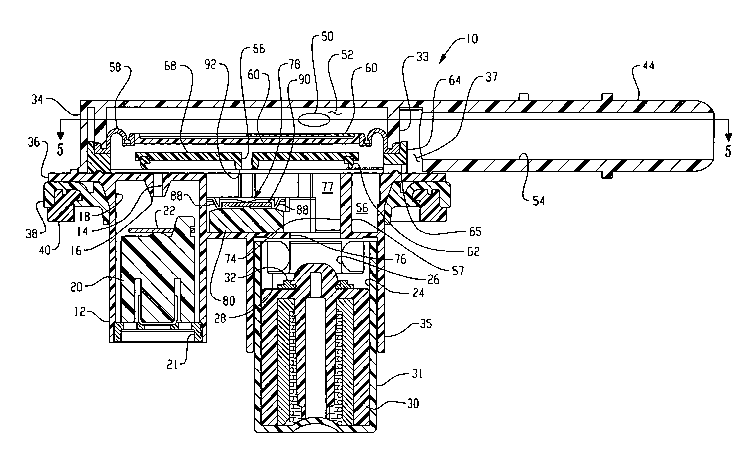
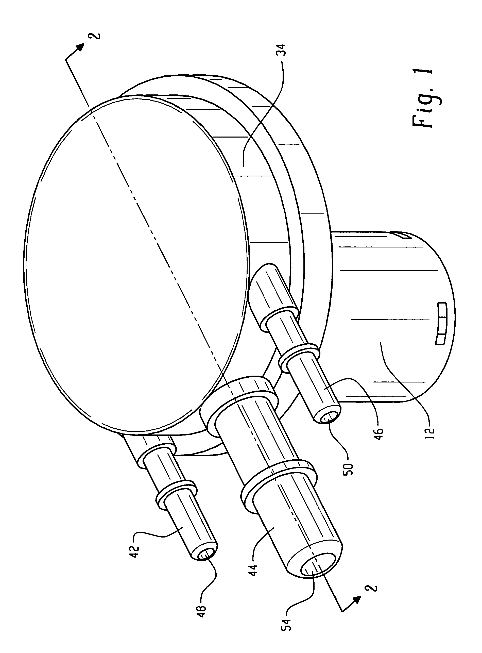
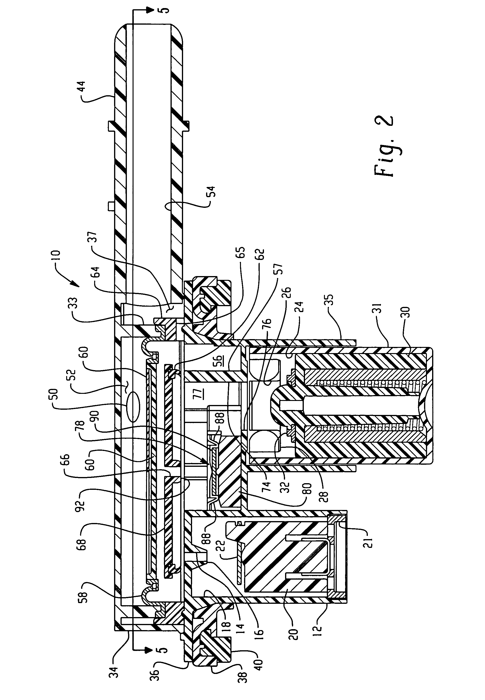
[0016]Referring to FIGS. 1 through 3, a multifunction valve assembly indicated generally at 10 and includes a valve body 12 which has formed therein a first vapor vent passage 14 having a valve seat 16 on the end of passage 14. The valve seat 16 is disposed at a first level with respect to the positioning of the valve through an access opening (not shown) through the wall of an unshown fuel tank.

[0017]The valve body 12 defines a first float chamber 18 which has disposed therein a float 20 which has a flexible resilient valve member 22 disposed on the upper end of the float for closing port 14 when the valve float rises and valve member 22 seats on valve seat 14.

[0018]Valve body 12 further defines a second valving chamber 24 having a second vent passage 26, larger than passage 14, and which has the lower end thereof forming a valve seat 28 which is disposed at a lower level with respect to valve seat 16. A float assembly 30 is slidably disposed in the chamber 24; and, float 30 has a ...


PUM


Abstract

A float assembly for a multifunction fuel vapor vent valve with a float having a recess formed in the upper surface of the float with a slot formed in the side of the float and communicating with the recess. A raised surface portion is formed in the bottom of the recess and downwardly extending projections are formed in the slot at the recess. A flexible wafer like valve disk is inserted in the slot and deformed or curled to pass under the projections and over the raised surface and into the recess. When fully received in the recess the disk returns to its flat configuration; and, the downward projections prevent removal without distortion. Radially inwardly projections about the recess retain the disk for limited lost motion in the direction of float movement.

Description

BACKGROUND OF THE INVENTION[0001]The present invention relates to vapor vent valves for fuel tanks and particularly valves of the type that are float operated for controlling flow of fuel vapor from the tank to a storage device such as a canister filled with granulated carbonaceous material.[0002]In providing such float operated vent valves for a motor vehicle fuel tank, it has been desired to provide multiple function valves in a common assembly for attachment to the tank through a single access opening in order to minimize the vapor permeation at the attachment. Such multiple function valves have included a plurality of float operated valves intended to close different sized vent ports at different levels of liquid fuel in the tank during refueling and in response to fuel sloshing in the tank during vehicle operation.[0003]Typically, such multifunctional float operated valves require a substantial range of float, size, movement and buoyancy such that the float housing extends into...

Claims


Application Information

Patent Timeline
Patent Type & Authority Patents(United States)
IPC IPC(8): F16K24/04
CPCF16K24/044Y10T137/7426Y10T137/053Y10T137/3099Y10T137/6004B60K15/01
Inventor SPINK, KENNETH M.VERZYL, STEVEN H.
Owner EATON INTELLIGENT POWER LTD
Why Eureka
Try Eureka