Froth flotation process and apparatus

a flotation process and flotation apparatus technology, applied in the direction of spray nozzles, solid separation, wet separation, etc., can solve the problems of low efficiency of recovery of valuable particles above this size, uneven distribution of coarse particles in the froth, and ineffectiveness, so as to reduce the blocking of holes in the tray

Inactive Publication Date: 2007-01-16
UNIV OF NEWCASTLE RES ASSOCS
View PDF22 Cites 14 Cited by
  • Summary
  • Abstract
  • Description
  • Claims
  • Application Information

AI Technical Summary

Benefits of technology

[0029]vibrating the tray in such a manner as to shake loose particles which become caught in the holes in the tray.
[0030]Preferably the amplitude and frequency of vibration is selected to minimise blocking the holes in the tray by the particles.

Problems solved by technology

Flotation has not generally been applied to the flotation of particles above 300 to 500 micrometers, because the efficiency of recovery of valuable particles above this size is typically very low.
A difficulty with the attempts that have been made in the past to float coarse particles in the froth, is that the slurry incorporating the coarse particles was introduced on to the upper surface of the froth from a central distribution point.
However, this results in a very uneven distribution of coarse particles in the froth and has not been found to be effective.
One of the problems inherent in the froth flotation process is the entrainment of unwanted matter by the bubbles rising into the froth layer.
These particles report to the froth concentrate leaving the cell, and cause a reduction in the quality or grade of the flotation product.
It will be understood that any apparatus involving the passage of the wash water through small holes or orifices will be prone to blocking by adventitious particles which may be present in the wash water, giving rise to a reduction in the efficiency of distribution of the wash water, and requiring frequent maintenance and inspections to prevent or remove blockages.
In practice, it can be difficult to obtain clean process water in coal washeries and mineral concentrator plants for use as wash water.

Method used


Image

  • Froth flotation process and apparatus
  • Froth flotation process and apparatus
  • Froth flotation process and apparatus

Examples


example

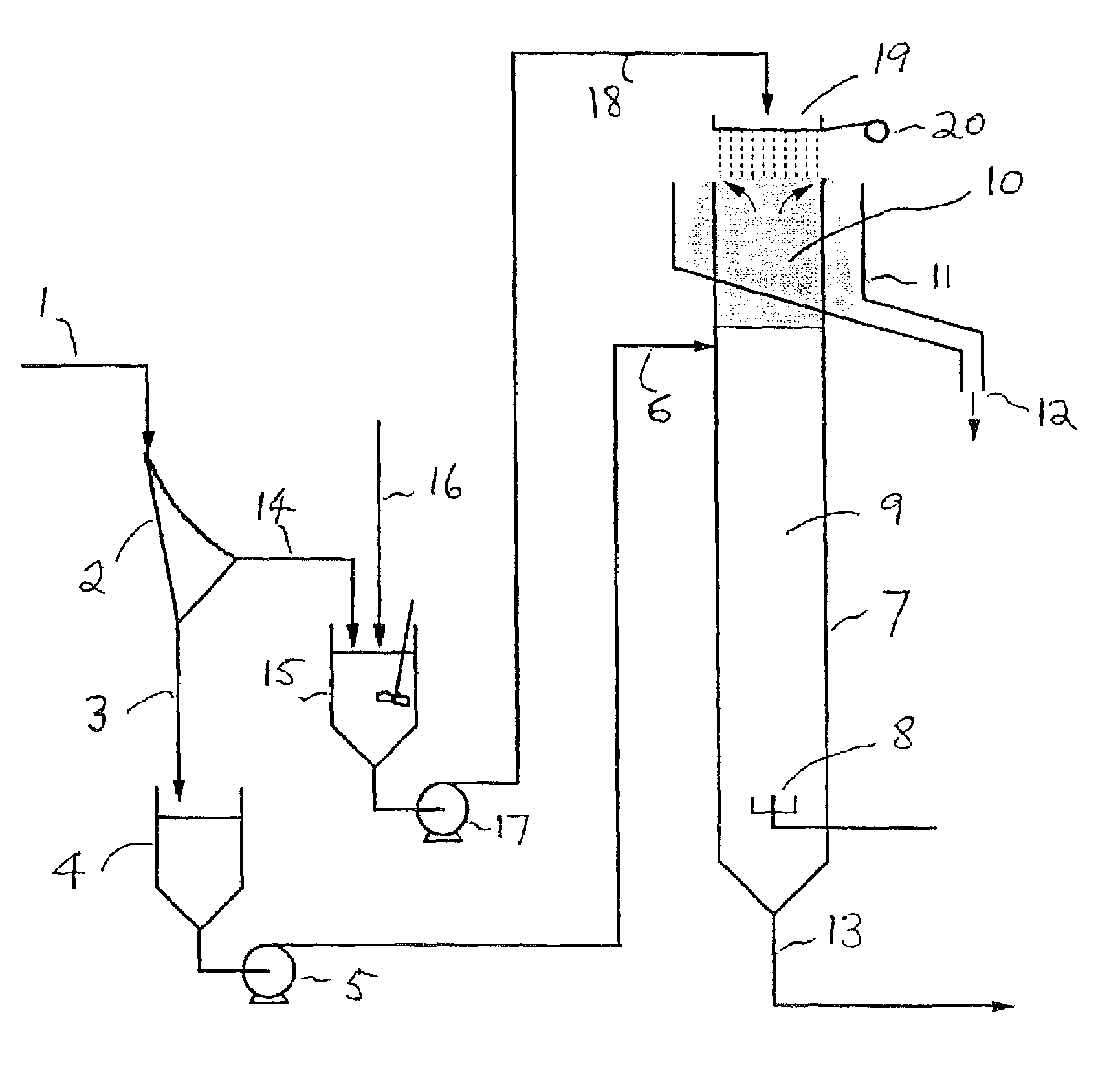
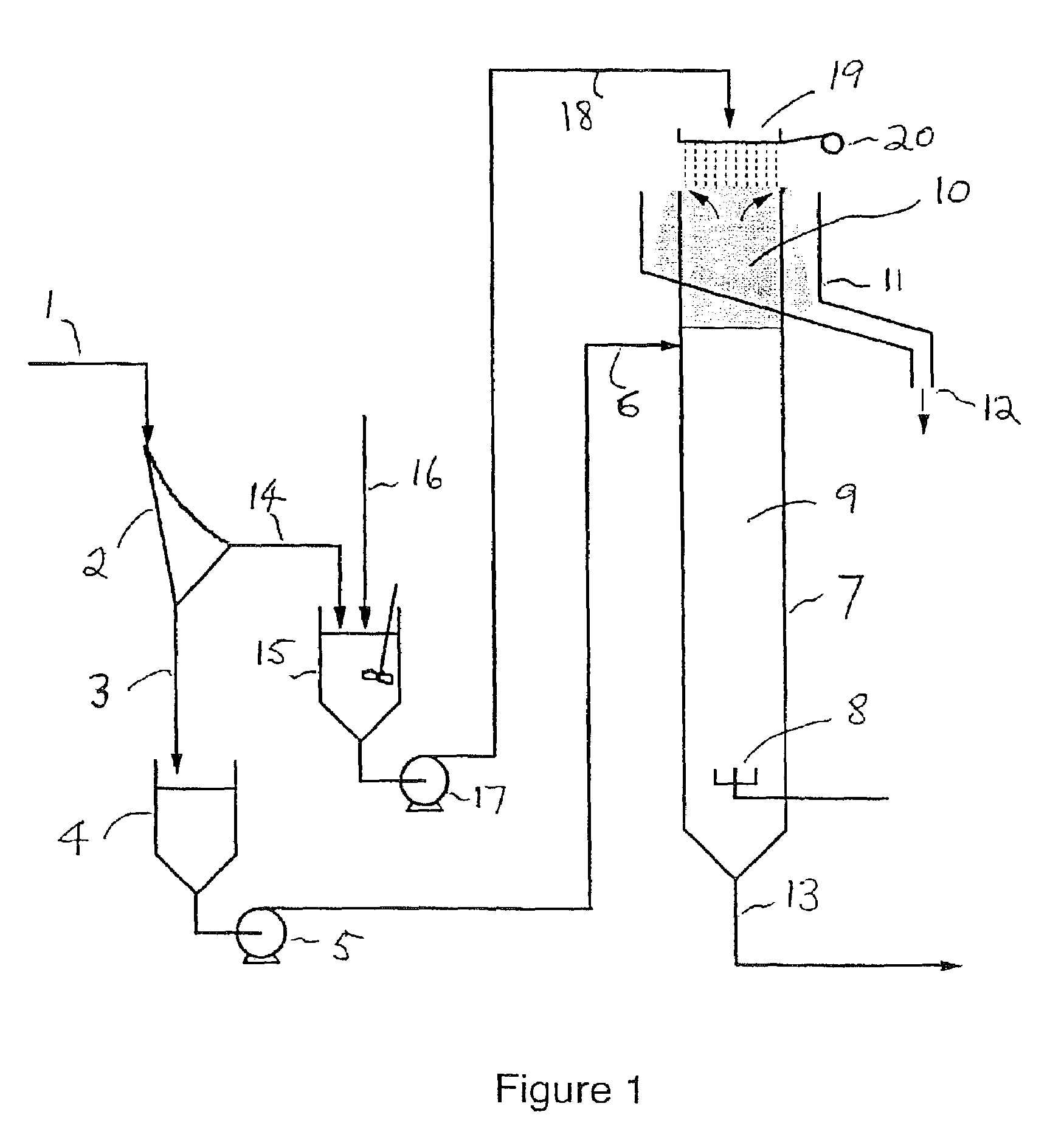
[0070]A plant was modified in accordance with the invention, and a feed of coal containing a wide range of particle sizes was fed to the unit. The suspension of feed coal at 5 percent W / W was conditioned with diesel oil (1 kg / tonne) and MIBC (methyl isobutyl carbinol) frother (15 gm / tonne of feed liquid). A sieve bend of nominal aperture 500 μm was used to separate the feed particles. The mass of feed above 500 μm in diameter was 16 percent. The coarse coal was distributed over the froth in the wash water. The superficial velocity of the air in the flotation cell (JG) was 1.2 cm / s, and the superficial velocity of the wash water applied to the cell (JL) was 1.1 cm / s. Analysis of the various streams on a size-by-size basis gave the results shown in Table 1. The recovery of the coarse combustibles was very high, almost matching the recoveries of the sub-500 μm particles.

[0071]

TABLE 1SizeSizeConcentrateTailingsMassCombustiblesUnderOverFeedAshAshYieldYieldμmμmAsh%%%%>20006.823.9727.33889...


PUM


Abstract

A froth flotation process typically used to separate particulate materials such as coal, has a mixed size feed (1) separated in a sieve bend (2) into a stream of relatively fine particles (3) and a stream of relatively coarse particles (14). The fine particles are fed to a flotation cell (7) in the normal manner, while the coarse particles are mixed with wash water (16) and distributed onto or into the froth layer (10) by wash water distribution apparatus (19, 20). Alternative variations of wash water distribution apparatus able to handle coarse particles are also described.

Description

FIELD OF THE INVENTION[0001]The present invention relates to a froth flotation process and apparatus in which small air bubbles are used in a flotation cell to selectively separate particles such as fine coal or minerals from unwanted material. It also relates to a process and apparatus for the distribution of water or slurry on top of the froth in such froth flotation processes.BACKGROUND OF THE INVENTION[0002]In a froth flotation process, the material to be processed is present in a suspension in water. A reagent is added which renders the particles to be separated hydrophobic or non-wetting with water. This reagent is known as a “collector”. Air bubbles are introduced into the suspension in a flotation cell or column, and on being brought into contact with the particles by collision, attach to the hydrophobic particles and carry them to the surface of the liquid where they form a froth. The froth layer flows out of the flotation cell into a froth overflow launder. The particles w...

Claims


Application Information

Patent Timeline
Patent Type & Authority Patents(United States)
IPC IPC(8): B03D1/02B03D1/14B03B11/00
CPCB03D1/02B03D1/14B03D1/085B03D1/082B03D1/24
Inventor JAMESON, GRAEME JOHNLAMBERT, NOEL WILLIAM ALEXANDER
Owner UNIV OF NEWCASTLE RES ASSOCS
Why Eureka
Try Eureka