Cross joint

Inactive Publication Date: 2007-01-16
JTEKT CORP
View PDF10 Cites 6 Cited by
  • Summary
  • Abstract
  • Description
  • Claims
  • Application Information

AI Technical Summary

Benefits of technology

[0012]According to the above-described cross joint, by subjecting the race portion and the shoulder portion of the cross shaft member to roller burnishing, the hardness of each of surfaces of the race portion and the shoulder portion can be increased and a residual compressive stress immediately below the surface can be increased. Further, a roughness of each of the surfaces can also be decreased.
[0013]According to the cross joint, the hardness of the surface of the race portion of the outer ring membe

Problems solved by technology

However, when large torque acts on the cross joint such as in the steel rolling mill, the joint is used under a very severe condition and there is a concern that even when the bearing steel is used, malfunction is brought about at an early stage.
Further, according to the cross member, since the roll and

Method used


Image

  • Cross joint
  • Cross joint
  • Cross joint

Examples


Embodiment Construction

[0019]A preferable embodiment showing a cross joint of the invention will be explained in reference to the drawings as follows. Further, in the following explanation, an explanation will be given of a case of applying the invention to a cross joint for driving a roll integrated into a steel rolling mill.

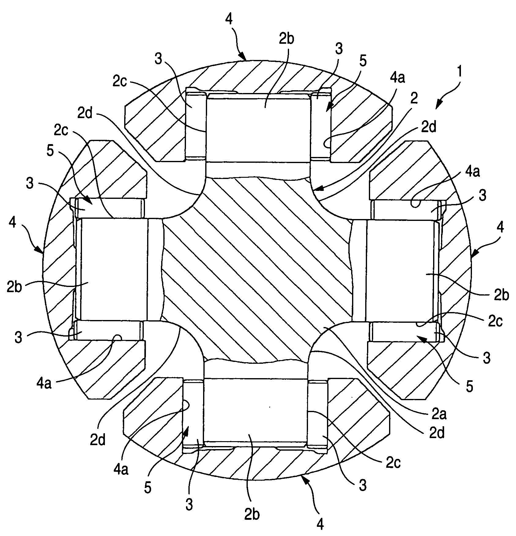
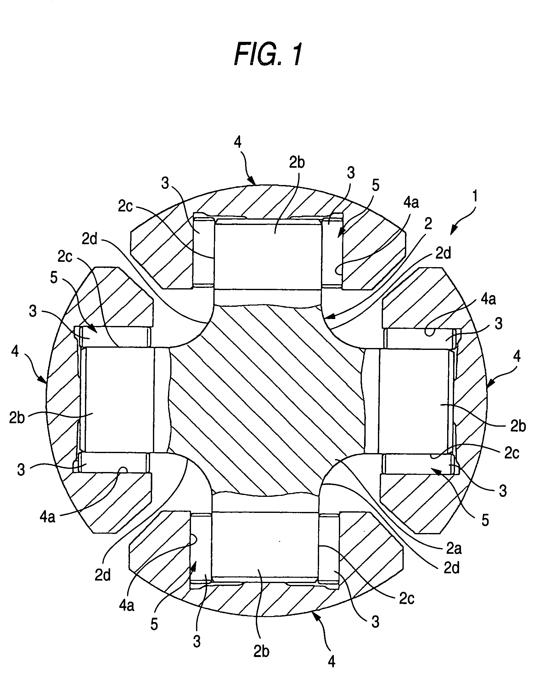
[0020]FIG. 1 is an outline sectional view showing an essential portion of a cross joint according to an embodiment of the invention. In the drawing, a cross joint 1 according to the embodiment is provided with a cross shaft member 2 integrally constituted with a base portion 2a and four shafts 2b arranged to project from the base portion 2b in a cross-like shape, and roller bearings 5 each having a bearing cup 4 as an outer ring member outwardly fitted to an outer side of an outer periphery of each of the shafts 2b via cylindrical rollers 3.

[0021]The outer peripheral portions of the respective shafts 2b of the cross shaft member 2 are formed with inner ring race portions 2c with whic...


PUM

PropertyMeasurementUnit
Lengthaaaaaaaaaa
Lengthaaaaaaaaaa
Lengthaaaaaaaaaa

Abstract

In a cross joint (1) outwardly fitting a bearing cup (outer ring member 4) to each of four pieces of shafts 2b of a cross shaft member (2) via a cylindrical member (rolling member 3), race portions (2c, 4a) formed on a side of the cross shaft member (2) and on a side of the bearing cup (4) and a shoulder portion (2d) provided between respectives of neck portions of two of the shafts (2b) of the cross shaft member (2) contiguous to each other are subjected to roller burnishing.

Description

BACKGROUND OF THE DISCLOSURE[0001]The present invention relates to a cross joint (joint cross coupling, universal joint) used in a steel rolling mill or the like.[0002]In, for example, a steel rolling mill, a cross joint is interposed between a roll and a drive shaft for driving to rotate the roll, a steel rolling processing of the steel material can be carried out by rotating to move the role in accordance with rotation of the shaft while the roll is allowed to move in an up and down direction relative to a steel material which is being rolled. The cross joint includes: a cross shaft member (cross) having four shafts arranged in a cross-like shape; and a cross bearing which has a plurality of cylindrical rollers as rolling members aligned at surroundings of the respective shafts of the member, and a bearing cup as an outer ring mounted to an outer side of outer peripheries of the rollers. Each of outer peripheral portions of the shafts is used as an inner ring race portion. Further...

Claims


Application Information

Patent Timeline
IPC IPC(8): F16D3/40F16D3/26B24B39/00F16D3/16F16D3/41
CPCB24B39/00Y10S464/902B22F2003/166F16D3/41F16D2200/0021F16D2250/0038F16D2300/10
Inventor KOMEYAMA, NOBUOOZEKI, MITSUMASA
Owner JTEKT CORP
Why Eureka
Try Eureka