DNA hybridization device and method

a hybridization device and technology of dna, applied in the field of hybridization, can solve the problems of high complexity, ineffective dna hybridization test, complex steps used in the prior art, etc., and achieve the effect of reducing pressure within the chamber

Active Publication Date: 2007-01-16
NANOSPHERE INC
View PDF16 Cites 28 Cited by
  • Summary
  • Abstract
  • Description
  • Claims
  • Application Information

AI Technical Summary

Benefits of technology

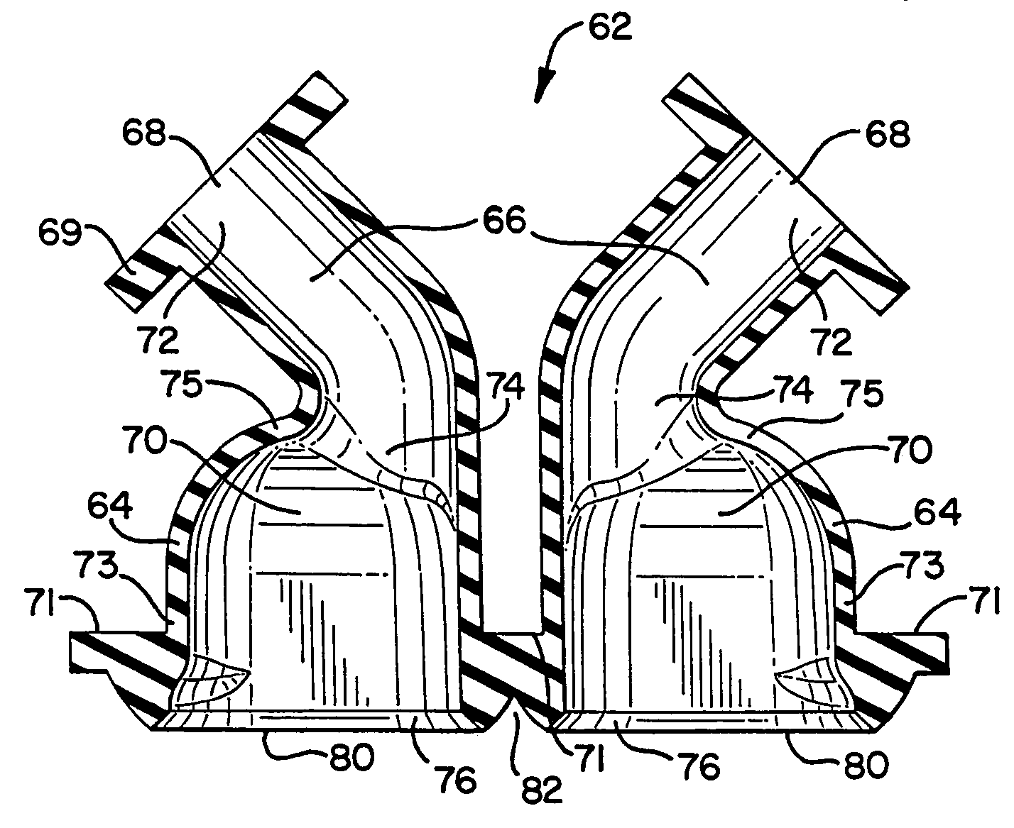
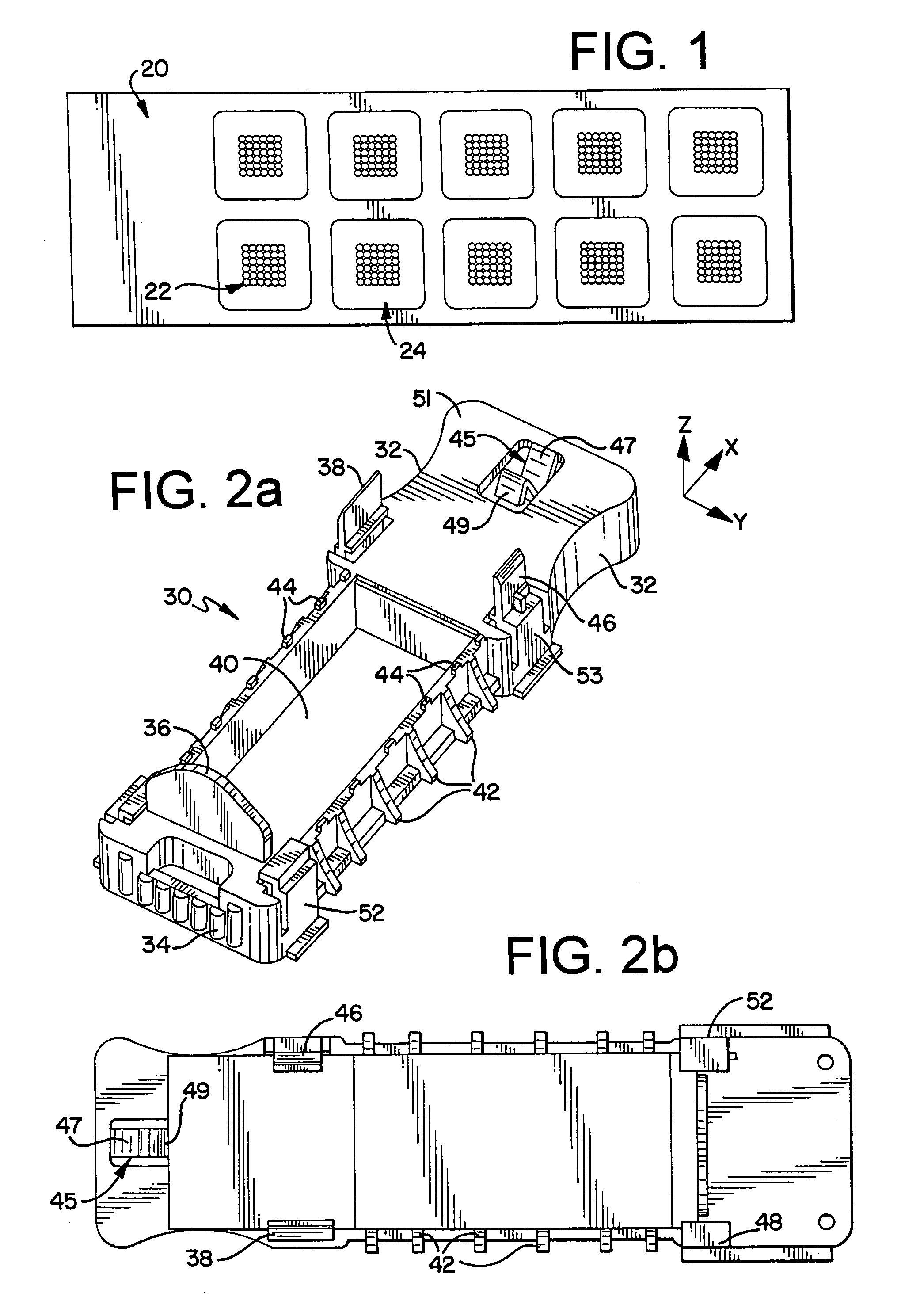
[0016]The at least partially pliable material may abut the substrate in a variety of ways. One such way is by placing a rigid material which abuts with the partially pliable material. The rigid material may then be attached (either permanently or temporarily) with the substrate or with another material which holds the substrate, such as a substrate holder, so that the pliable material may form a seal with the upper surface of the substrate. The rigid material may, in one embodiment, act as a cover for the pliable material and may abut only a portion of the material. For example, an airspace may be formed between the rigid material and the at least partially pliable material (such as between one of the sidewalls and the rigid material). In this manner, the sidewall may expand into the airspace in order to reduce pressure within the chamber. The rigid material may further provide structure for the openings of the chamber. The pliable material may include an opening lip, the opening lip being adjacent to the opening, so that the rigid material may abut at least a portion of the opening lip to provide structure for the opening.

Problems solved by technology

These steps used in the prior art are complex, but the process can be manually controlled when only a single sample is being tested.
This results in high amounts of complexity as many tubes laid out in rack systems must all be tracked by the user as they sequentially remove the correct volumes of solutions from each tube and placed it in another corresponding tube or in a specific area of the hybridization slide.
It is common for mistakes in micropipetting, spatial mapping or task sequencing to render a DNA hybridization test useless.
The prior art manual process is also difficult to control thermally.

Method used


Image

  • DNA hybridization device and method
  • DNA hybridization device and method
  • DNA hybridization device and method

Examples


Embodiment Construction

[0054]As discussed in the background section, hybridization should be performed under precise temperature and humidity conditions. The hybridization may comprise, in one aspect, capture probes bound to a substrate. The capture probes may be DNA capture probes, as discussed in the background section. Alternatively, the capture probes may be RNA capture probes. The capture probes may form a complex with a target analyte. The target analyte may be a nucleic or non-nucleic acid. The target analyte may further bind to a detection probe, such as a nanoparticle detection probe, as discussed in the background section. The hybridization may comprise, in another aspect, target analyte(s) bound to a substrate. The target analyte (e.g., nucleic or non-nucleic acid) may thus form a complex with a capture probe, and may further bind with a detection probe, such as a nanoparticle detection probe.

[0055]Prior art devices used for hybridization of a substrate resulted in difficulties in controlling c...


PUM

PropertyMeasurementUnit
angleaaaaaaaaaa
angleaaaaaaaaaa
sizesaaaaaaaaaa

Abstract

An apparatus and method for DNA hybridization is provided. The apparatus and method work in conjunction with a substrate comprising an upper surface having probes. The apparatus may comprise a material which abuts the substrate, with at least a portion of the material being pliable. The material and the substrate form a plurality of chambers, each chamber having a bottom including at least a portion of the upper surface, at least one sidewall, and an opening. The apparatus further comprises a mechanism for closing the openings of the chambers, thereby sealing the chambers.

Description

REFERENCE TO RELATED APPLICATIONS[0001]The current patent application claims priority to U.S. patent application Ser. No. 60 / 352,346 filed on Jan. 28, 2002 and entitled “DNA Hybridization Device and Method.” The current patent application also claims priority to U.S. patent application Ser. No. 60 / 426,316 filed on Nov. 14, 2002 and entitled “DNA Hybridization Device and Method.” This application incorporates by reference U.S. patent application Ser. No. 60 / 352,346 and U.S. patent application Ser. No. 60 / 426,316 in their entirety.FIELD OF THE INVENTION[0002]This present invention relates to hybridization. More specifically, the invention provides for methods and apparatuses for hybridization of DNA.BACKGROUND OF THE INVENTION[0003]Sequence-selective DNA detection has become increasingly important as scientists unravel the genetic basis of disease and use this new information to improve medical diagnosis and treatment. DNA hybridization tests on oligonucleotide-modified substrates are...

Claims


Application Information

Patent Timeline
Patent Type & Authority Patents(United States)
IPC IPC(8): C12M3/00C12M1/00B01L3/00
CPCB01L3/5055B01L3/5085B01L3/50853B01L3/502B01L2200/026B01L2300/0858B01L2300/042B01L2300/0636B01L2300/0809B01L2300/0822B01L2200/0689
Inventor PATNO, TIMOTHYFISHER, MARKMAUNG, GEORGE KYAW SOEWESTBERG, TOM
Owner NANOSPHERE INC
Why Eureka
Try Eureka