Measuring fiber orientation by detecting dispersion of polarized light

a technology of polarized light and fiber orientation, which is applied in the direction of optical radiation measurement, instruments, papermaking, etc., can solve the problems of dimensional instability, twisting, curling, and skewing, defective products, etc., and achieves higher resolution, simple and robust construction, and reliable measurement results.

Active Publication Date: 2007-01-16
HONEYWELL INT INC
View PDF49 Cites 24 Cited by
  • Summary
  • Abstract
  • Description
  • Claims
  • Application Information

AI Technical Summary

Benefits of technology

[0032]The present invention for measuring fiber orientation simultaneously illuminates a surface of the web with a plurality plane-polarized light beams. As a corollary, the inventive technique exhibits important advantages over the prior art, including, for instance: (i) it does not require moving parts, such as rotating polarizers or rotating detectors, so that its construction is simpler and more robust; (ii) it is not vulnerable to fast variations in the anisotropy of the web, so that the measurement results are more reliable; (iii) it provides a higher resolution measurement in the time domain; (iv) it is not sensitive to positional or geometric changes in the plane of the measured sheet relative to the measuring device; and (v) in the case of a scanning measurement, it can provide higher resolution measurements in the position domain.

Problems solved by technology

In particular, if the fiber orientation distribution is incorrect, then dimensional instability in the form of twist, curl, and skew will occur, and strength axes will not correspond to manufacture axes.
This leads to defective products such as paper that jams in printers / copiers, packaging that jams in discrete item containers, and boxes which lean or collapse when stacked.
Because the spot illumination area is relatively small, these techniques do not necessarily yield representative measurements for the sheet.
The abovementioned methods produce unreliable estimates of the fiber orientation angle and the fiber orientation anisotropy, if the fiber orientation distribution of the sheet is not unimodal or is not symmetric.
Moreover, they can produce biased results if the sheet surface is unconsolidated such that there are fibers partly protruding from the sheet, or if the sheet surface roughness has high amplitude at millimeter scales.
This laboratory process is labor-intensive and not applicable to on-line measurements of moving webs.
Therefore, despite the asserted advantages associated with these fiber orientation measurement systems, none of these apparatuses affords a simple, robust, and accurate device for on-line fiber orientation measurements of a moving web or sheet made of nonwoven components.

Method used


Image

  • Measuring fiber orientation by detecting dispersion of polarized light
  • Measuring fiber orientation by detecting dispersion of polarized light
  • Measuring fiber orientation by detecting dispersion of polarized light

Examples


Embodiment Construction

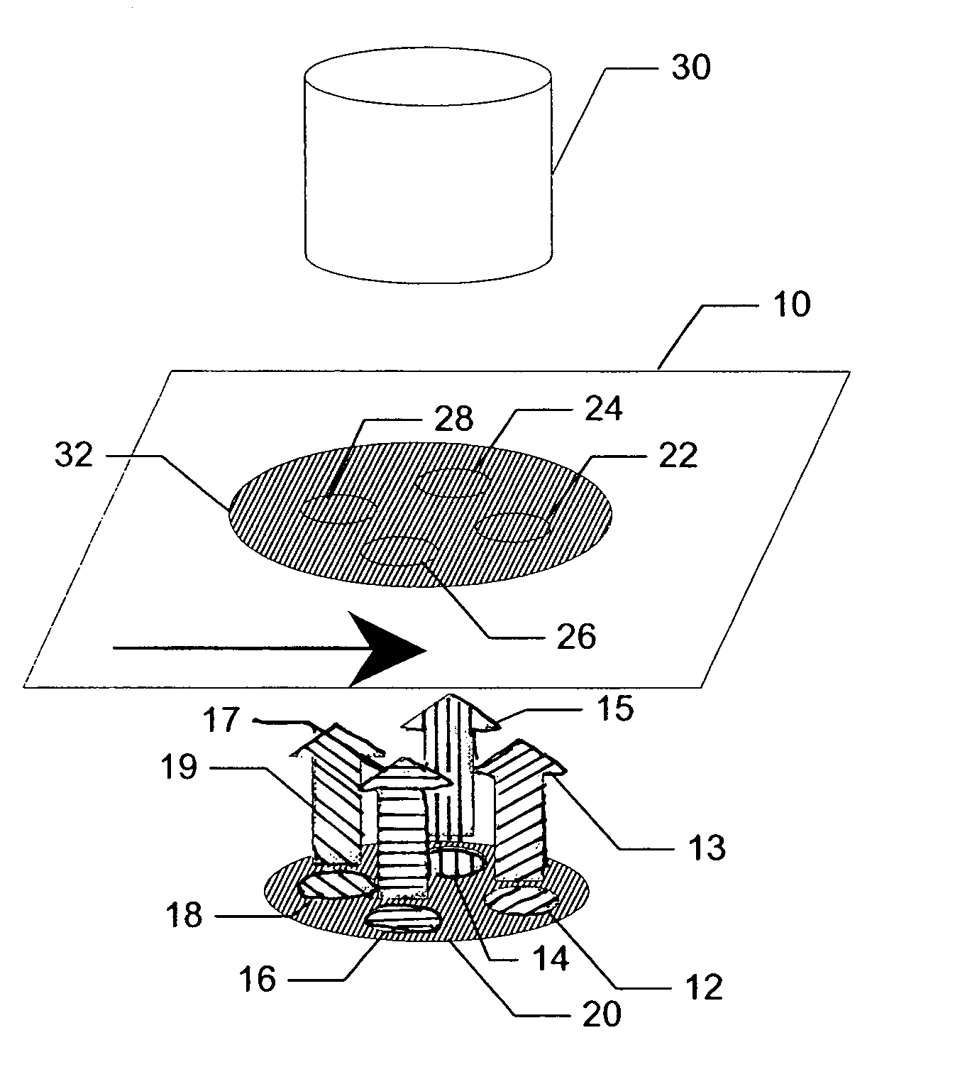
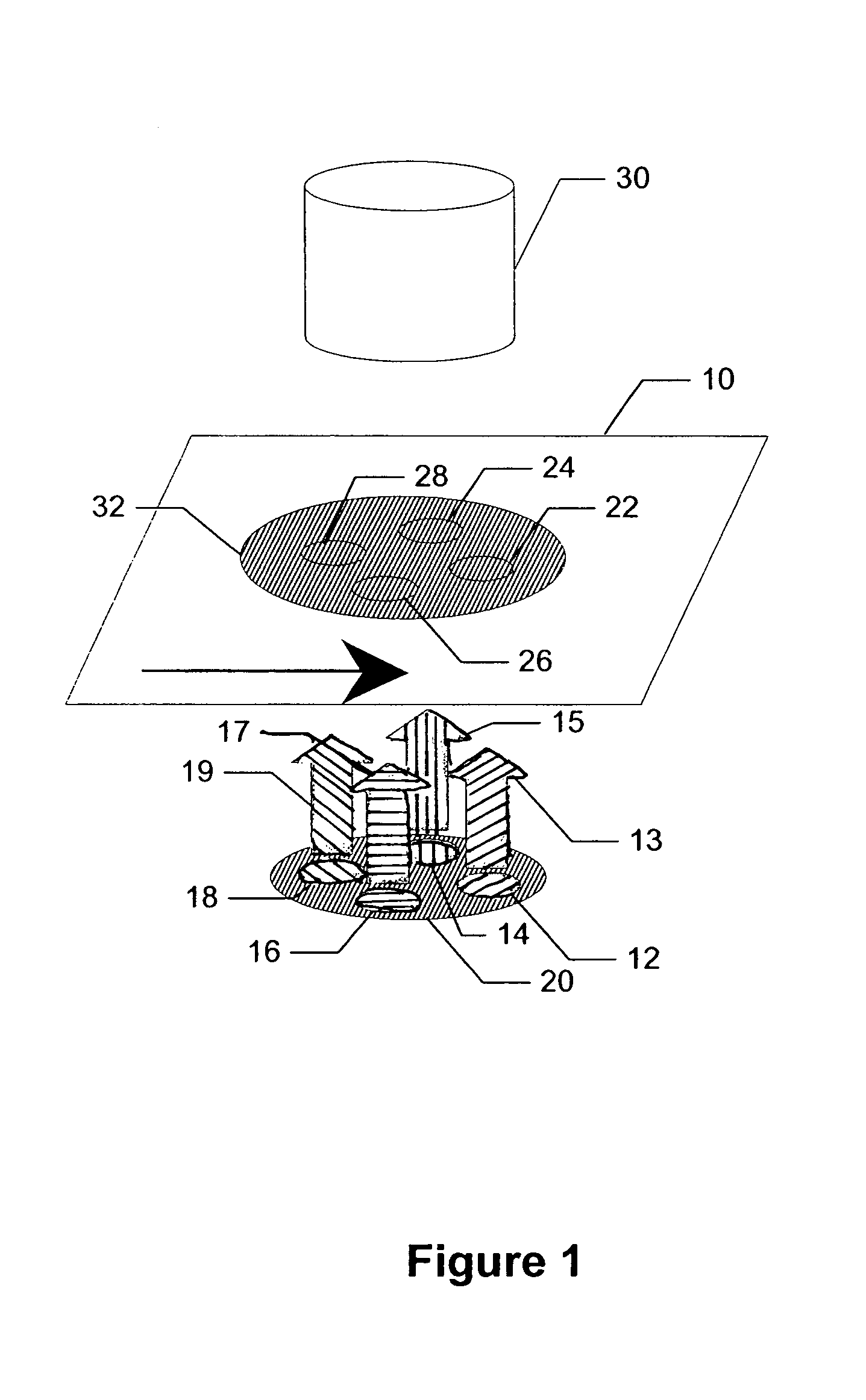
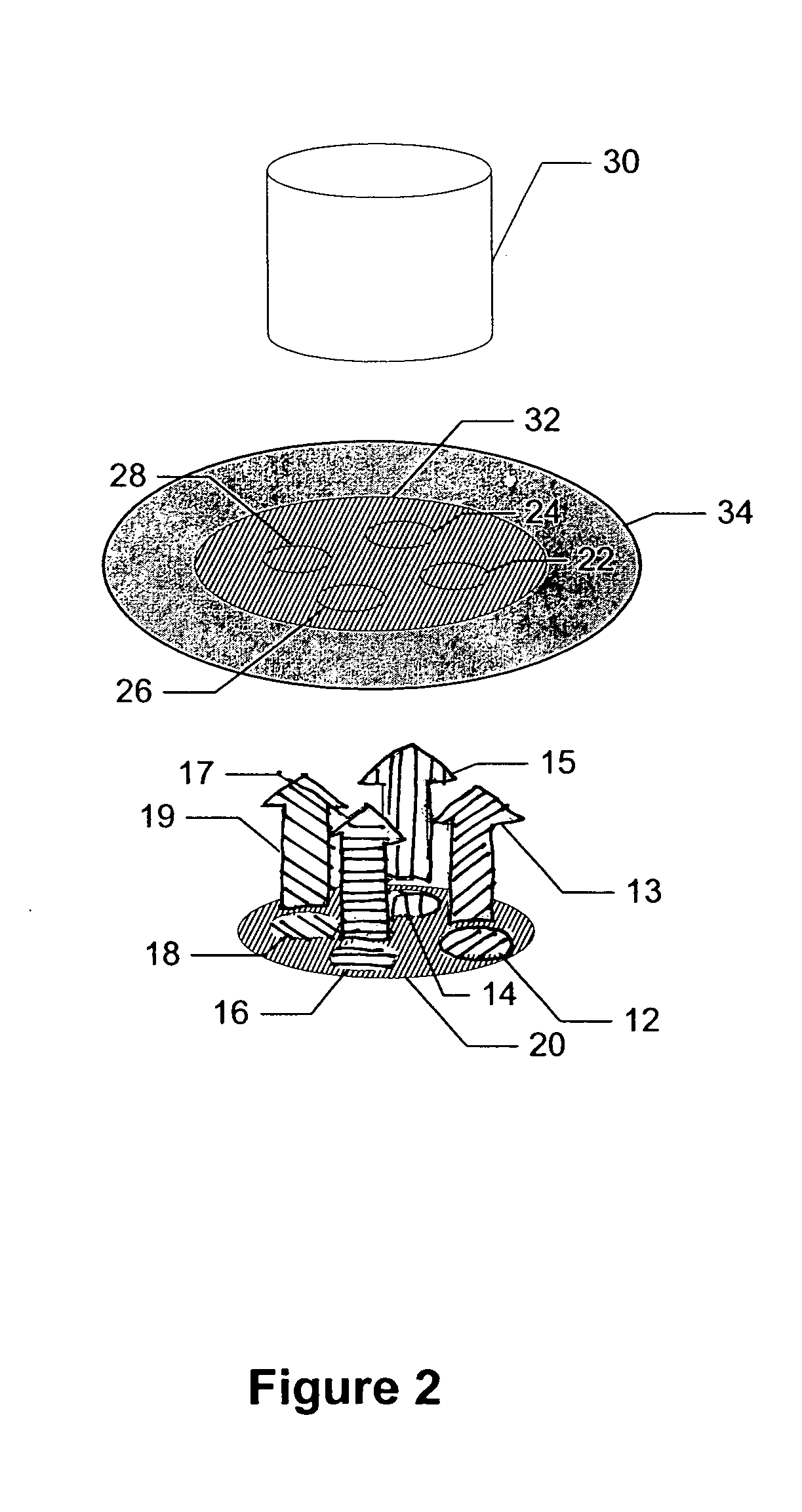
[0056]The present invention relates to methods and devices for calculating the fiber orientation in nonwoven materials especially where the material is in the form of a moving web, film or sheet. The fiber orientation of the whole thickness of the web of the web can be measured. The fiber orientation measurements can be expressed as one or more different parameters that are used in controlling the papermaking process and / or characterizing the properties of the product. The parameters include, for instance: average fiber orientation angle and fiber orientation anisotropy index. In addition, the fiber orientation measurements from both sides of the web can yield information regarding curl and twist deformations of the web, e.g., paper.

[0057]While the invention will be illustrated in measuring fiber orientation of paper, it is understood that the invention can be employed to analyze fiber orientation in a variety of products that are formed from non-woven fibrous materials including, f...


PUM

PropertyMeasurementUnit
wavelengthsaaaaaaaaaa
wavelength rangeaaaaaaaaaa

Abstract

An image-based technique that measures the orientation of fibers in a moving web of nonwoven material. At least four light spots on one side of the web are illuminated essentially simultaneously with at least four plane-polarized incident substantially perpendicular light beams having different polarization characteristics. Dispersion of the excident light spots is measured on the opposite side of the web along at least one linear section which is at a known angle relative to the plane of polarization of the corresponding plane-polarized incident light beam, wherein at least one such linear section lies substantially across the center of the transmitted excident light spot and extends substantially across the width of the transmitted excident light spot. Variations in the dispersion of the transmitted excident light spot for the at least four plane-polarized light beams are calculated, and the fiber orientation is estimated from the variations.

Description

FIELD OF THE INVENTION[0001]The present invention is directed to techniques of determining the fiber orientation in webs formed from non-woven materials and particularly to image-based measurements of the average the fiber orientation of paper using dispersion of linearly or plane-polarized light.BACKGROUND OF THE INVENTION[0002]In the manufacture of paper on continuous papermaking machines, a web of paper is formed from an aqueous suspension of fibers (stock) on a traveling mesh, papermaking fabric, or wire and water drains by gravity and suction through the fabric. The web is then transferred to the pressing section where more water is removed by pressure and vacuum. The web next enters the dryer section where steam heated dryers and hot air completes the drying process. The paper machine is, in essence, a water removal, system. Papermaking devices well known in the art are described for example in Handbook for Pulp & Paper Technologists 2nd ed., G. A. Smook, 1992, Angus Wilde Pub...

Claims


Application Information

Patent Timeline
Patent Type & Authority Patents(United States)
IPC IPC(8): G01N21/89G01N21/21G01N21/86
CPCD21G9/0027G01N33/34G01N21/86G01N2021/8681
Inventor SHAKESPEARE, JOHN F.
Owner HONEYWELL INT INC
Why Eureka
Try Eureka