
Bridge-less boost (BLB) power factor correction topology controlled with one cycle control

a topology and power factor technology, applied in the direction of electric variable regulation, process and machine control, instruments, etc., can solve the problems of high conduction loss, undesirable topology, impracticality of implementation, etc., to eliminate the intrinsic loss of the input rectifier bridge, reduce the size of the system, and reduce the power dissipation

Inactive Publication Date: 2007-01-16
INTERNATIONAL RECTIFIER COEP
View PDF12 Cites 87 Cited by
  • Summary
  • Abstract
  • Description
  • Claims
  • Application Information

AI Technical Summary

Problems solved by technology

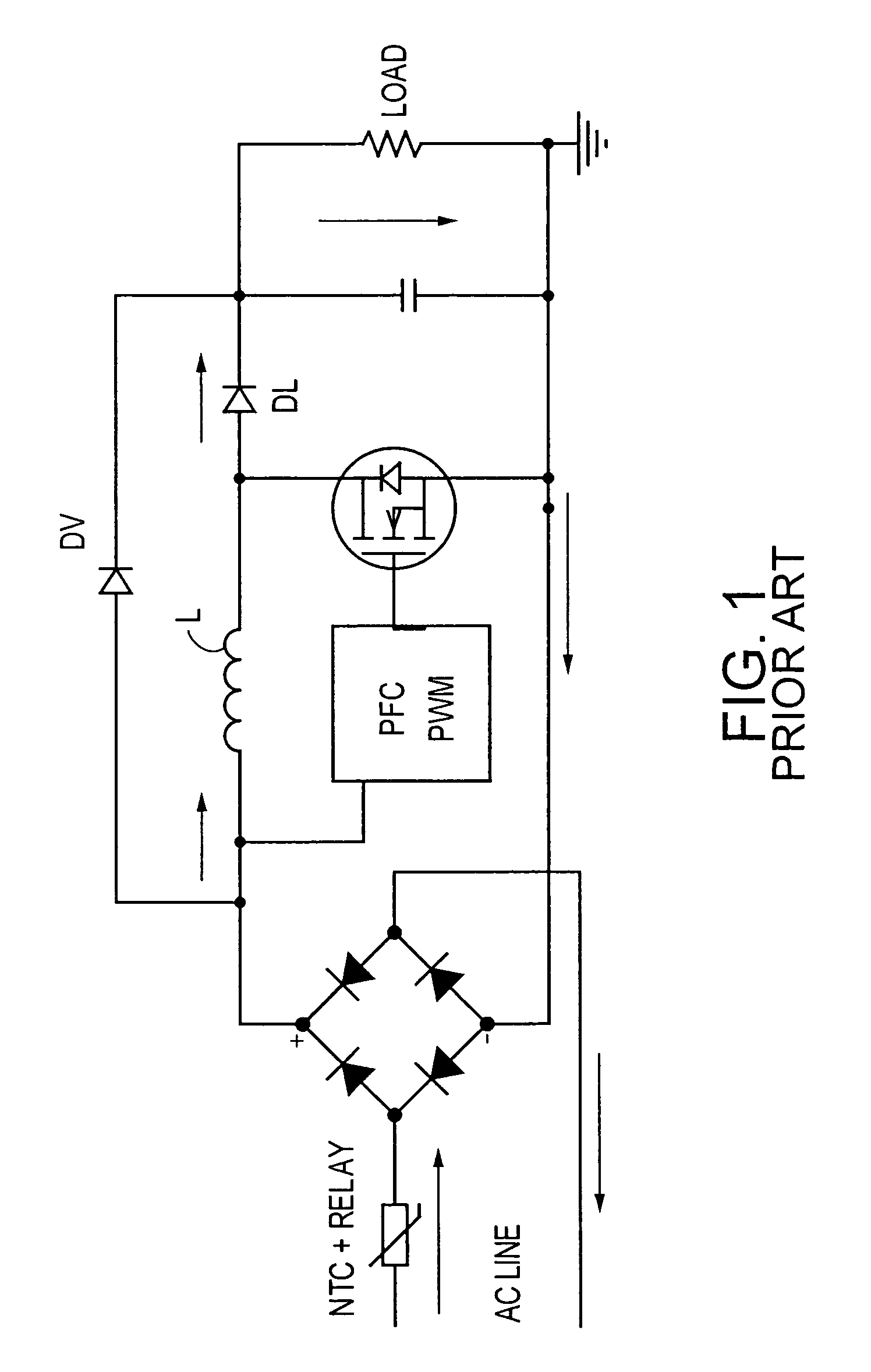
The path of the current goes through three diodes in series (two in the input bridge plus the output boost diode DL) causing high conduction losses especially at high current levels.
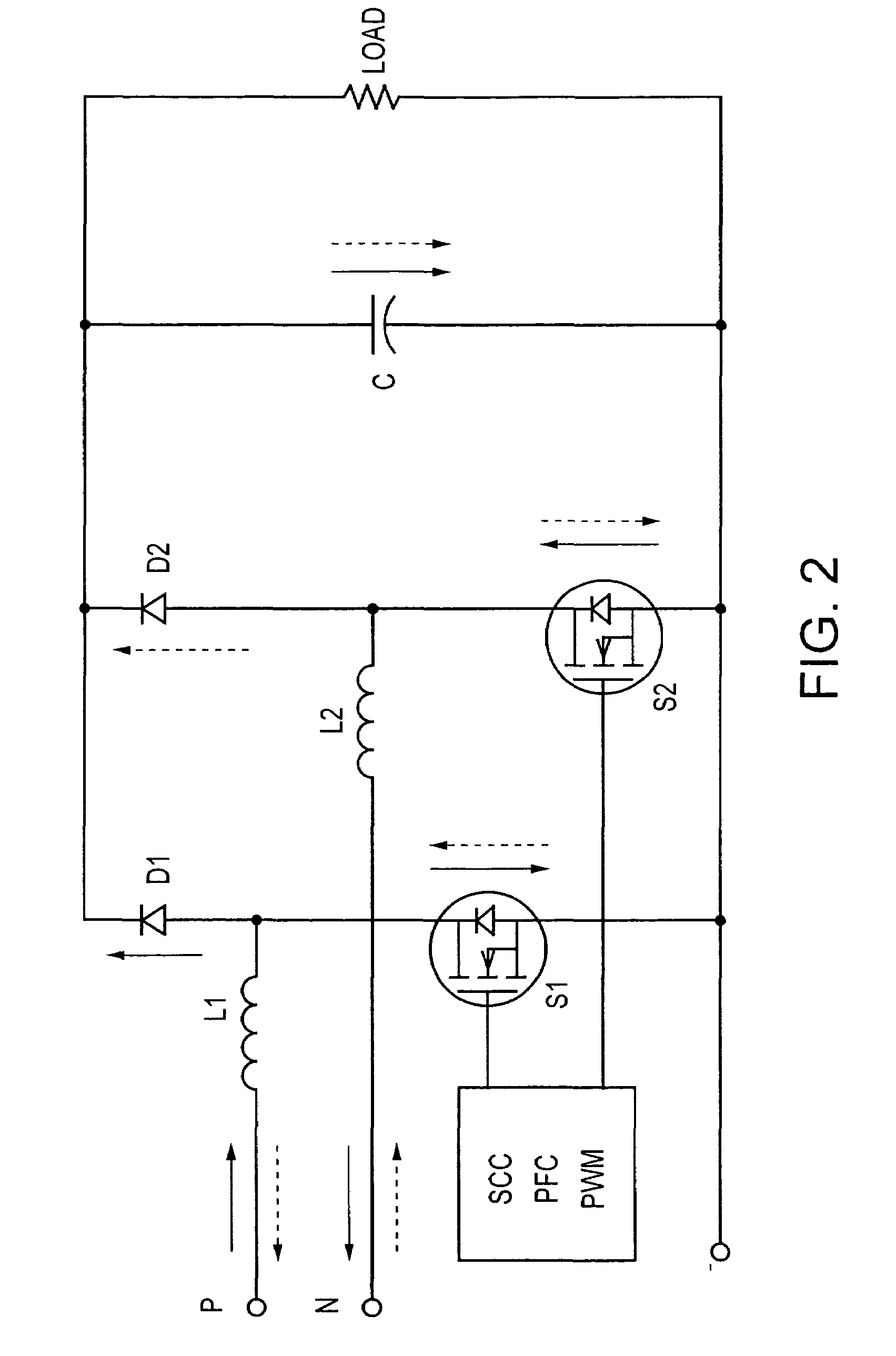
This topology is undesirable at least because the controlled switches cannot be driven at the same time, but need to have separate gate drives, properly out of phase.
A disadvantage of this circuit is the reverse recovery of the high side switch, which would make the implementation impractical.

Method used


Image

  • Bridge-less boost (BLB) power factor correction topology controlled with one cycle control
  • Bridge-less boost (BLB) power factor correction topology controlled with one cycle control
  • Bridge-less boost (BLB) power factor correction topology controlled with one cycle control

Examples


experimental implementation

[0087]D. Experimental Implementation

[0088]Based on the analysis above, the bridgeless PFC circuit can both simplify the circuit topology and improve the efficiency. Moreover, the one cycle control is the most attractive control method for the bridgeless PFC circuit. One 500W, 100 kHz switching frequency, universal line input bridgeless PFC circuit was designed and implemented with one cycle control. 600V 22 A super junction MOSFET and 600V 4 A SiC diode were used in the prototype. In addition, a conventional PFC circuit using same devices was built to serve as the benchmark.

[0089]The input voltage and current waveforms are shown in FIG. 23. The input current perfectly follows the input voltage. Thus the power factor correction function is achieved by using the one cycle controller. The efficiency comparison between these two circuits at 90V input line voltage is shown in FIG. 24. For the whole power range, efficiency improvement is around 1%, which is quite coincident with the theor...


PUM


Abstract

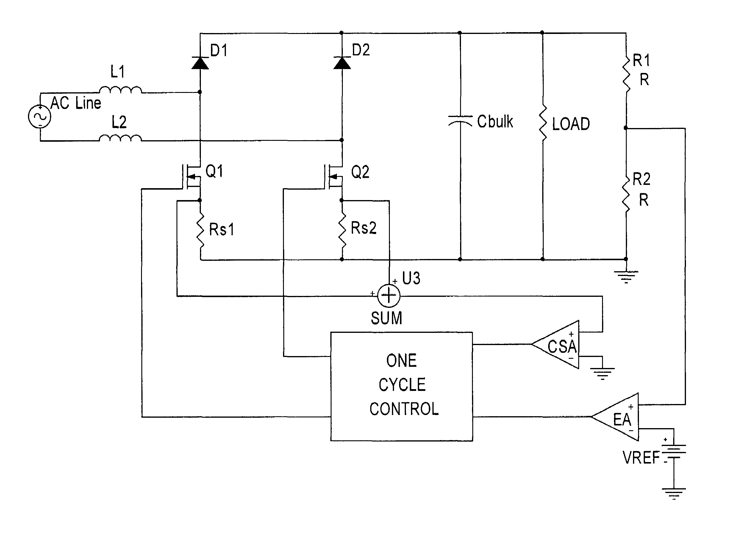
The bridgeless boost topology reduces the power dissipation, cost, and size of prior PFC systems by eliminating the intrinsic loss of the input rectifier bridge. Sensing of the input line voltage by the controller is unnecessary. The use of One Cycle Control (also known as Single Cycle Control) allows the Power Factor Correction function to be performed without complex rectification networks to obtain the AC line voltage reference. The use of bi-directional switches makes it possible to control inrush current (the startup over-current due to the charging of the output bulk capacitor), which allows elimination of over-current limiting devices and reduction of the diode surge capability requirements. Moving the boost inductor to the system input adds an additional filtering function, reducing the cost of input EMI filtering.

Description

CROSS-REFERENCE TO RELATED APPLICATION[0001]This disclosure is based upon and claims priority of U.S. Provisional Patent Application Ser. No. 60 / 507,901 filed Oct. 1, 2003, incorporated by reference.BACKGROUND OF THE INVENTION[0002]1. Field of the Invention[0003]The present invention relates to a bridge-less boost (BLB) power factor correction topology, and more particularly to such a circuit controlled with one cycle control and / or comprising bidirectional switches.[0004]2. Description of the Related Art[0005]Power factor correction is required by international standards (EN61000-3-2) to reduce harmonic emissions in AC powered systems.[0006]The most common solution, shown in FIG. 1, uses typically an input rectifier bridge, made of four diodes of appropriate voltage rating followed by a boost switching converter, controlled by a voltage loop and a current loop. The outer voltage loop via diode DV will tend to maintain the output voltage approximately constant. The inner current loo...

Claims


Application Information

Patent Timeline
Patent Type & Authority Patents(United States)
IPC IPC(8): H02M7/04G05FH02M3/335
CPCH02M1/4225H02M7/219Y02B70/126Y02B70/10Y02P80/10H02M1/4216H02M1/0085
Inventor SOLDANO, MARCO
Owner INTERNATIONAL RECTIFIER COEP
Learn More