Measurement module interface protocol database and registration system

a technology of interface protocol and registration system, applied in the field of measurement module interface protocol database and registration system, can solve the problems of inefficient, redundant and inefficient inclusion of pxi interface circuitry on each sensor, and high cost of each standard interface component on each module, so as to achieve small and cheaper

Active Publication Date: 2007-01-16
NATIONAL INSTRUMENTS
View PDF5 Cites 68 Cited by
  • Summary
  • Abstract
  • Description
  • Claims
  • Application Information

AI Technical Summary

Benefits of technology

[0017]This “adaptive interface” approach allows the measurement module to include only components necessary for providing the required functionality, i.e., the measurement module does not have to include hardware and software implementing standard interfaces for communication with external systems. Said another way, much of the interface responsibilities of the measurement module are assumed by the carrier, which itself is programmed by the computer system, thus the measurement module may be smaller and cheaper than typical functional modules.

Problems solved by technology

Often, the field signals may be coupled to high common-mode voltages, ground loops, or voltage spikes that often occur in industrial or research environments which could damage the computer system.
The inclusion of these standard interface components on each module may be expensive, and may also substantially increase the size of a given module.
Additionally, when multiple modules are used in a single system, such as a PXI based system fielding multiple sensors, the inclusion of PXI interface circuitry on each sensor is redundant and inefficient.
Finally, if multiple communication interfaces are desired for the modules, the expense and size of the modules may increase dramatically with the inclusion of each additional interface card.

Method used


Image

  • Measurement module interface protocol database and registration system
  • Measurement module interface protocol database and registration system
  • Measurement module interface protocol database and registration system

Examples


Embodiment Construction

Incorporation by Reference

[0061]The following U.S. Patents and patent applications are hereby incorporated by reference in their entirety as though fully and completely set forth herein.

[0062]U.S. Pat. No. 4,914,568 titled “Graphical System for Modeling a Process and Associated Method,” issued on Apr. 3, 1990.

[0063]U.S. Pat. No. 6,219,628 titled “System and Method for Configuring an Instrument to Perform Measurement Functions Utilizing Conversion of Graphical Programs into Hardware Implementations”.

[0064]U.S. Pat. No. 6,173,438 titled “Embedded Graphical Programming System” filed Aug. 18, 1997, whose inventors are Jeffrey L. Kodosky, Darshan Shah, Samson DeKey, and Steve Rogers.

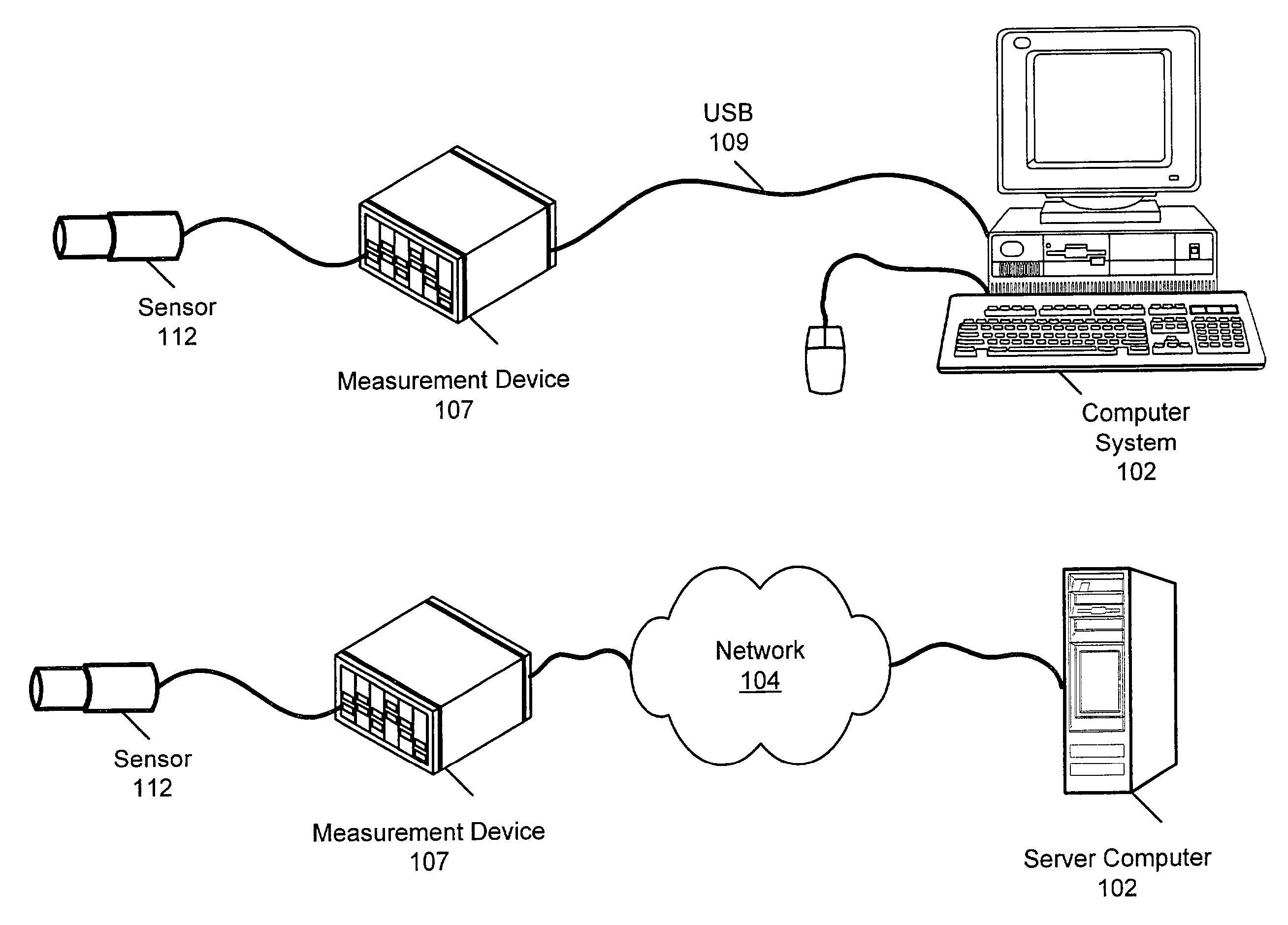
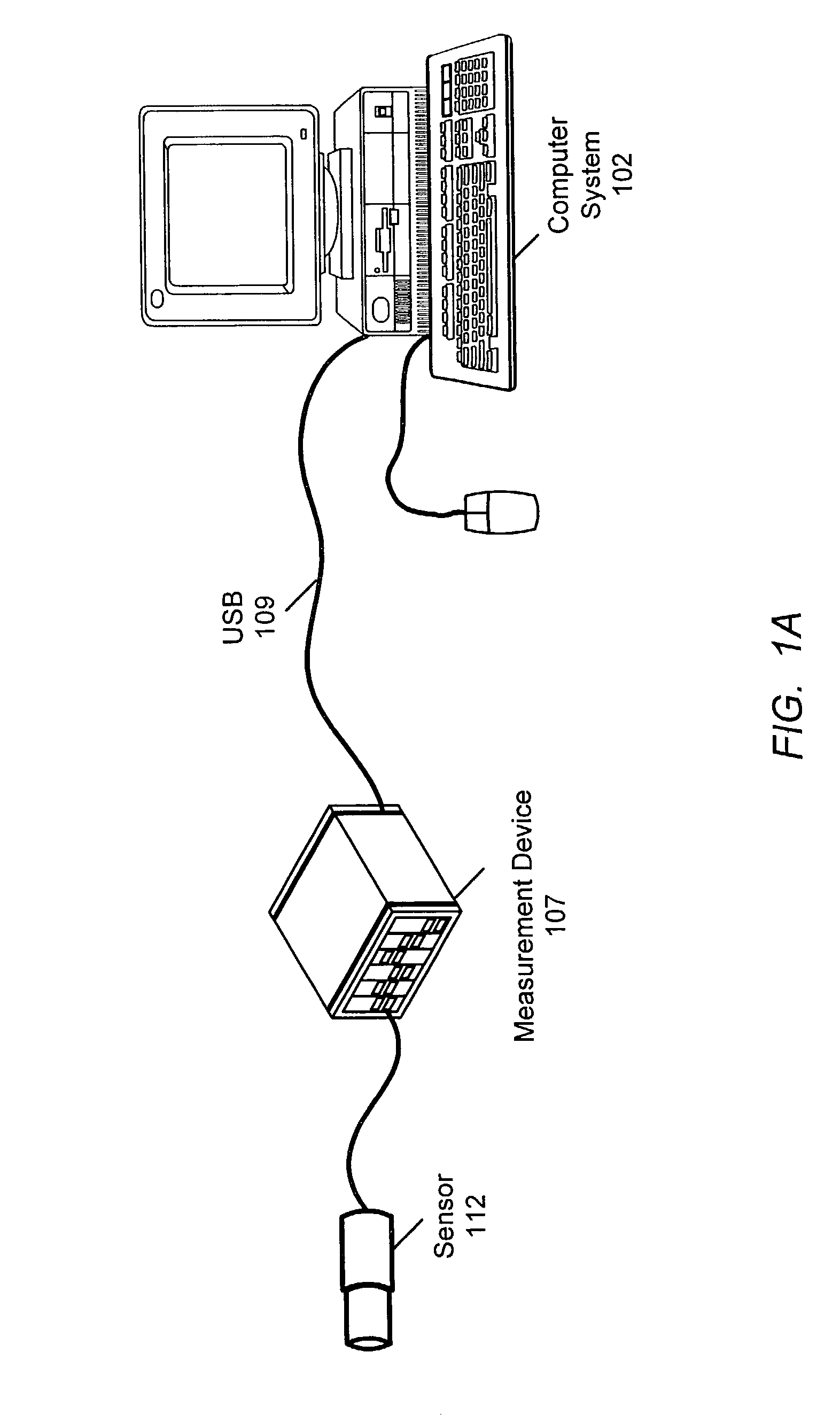
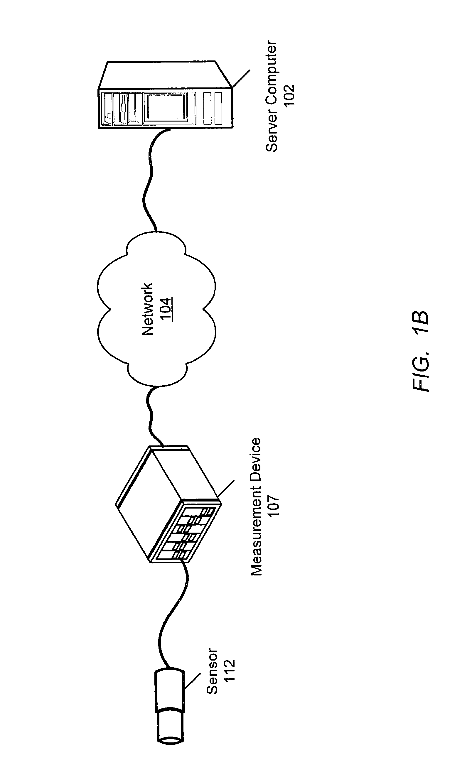
[0065]U.S. Provisional Patent Application Ser. No. 60 / 312,254 titled “Measurement System with Modular Measurement Modules That Convey Interface Information” filed on Aug. 14, 2001, whose inventors are Perry Steger, Garritt W. Foote, David Potter and James J. Truchard.

[0066]U.S. patent application Ser. No. 10 / ...


PUM


Abstract

System and method for providing a measurement module (MM) interface for configuring a measurement system. The method includes creating a MM and one or more MM interface programs implementing respective MM interface protocols (MMIP) for the measurement module. An MMIP server is accessed and the MM registered with the MMIP server. The MM interface programs are stored on the MMIP server, where they are each downloadable from the MMIP server and usable to program a functional unit on a carrier unit, enabling the carrier unit to communicate with the MM in accordance with the respective MMIP. A MM is installed in the measurement system and provides ID to a carrier unit of the system. The MMIP server is accessed and, based on the ID, payment information, etc., a MM interface program is downloaded and used to configure the carrier unit to enable communication with the MM in performing a task.

Description

PRIORITY CLAIM[0001]This application claims benefit of priority of U.S. provisional application Ser. No. 60 / 312,254 titled “Measurement System with Modular Measurement Modules That Convey Interface Information” filed on Aug. 14, 2001, whose inventors are Perry Steger, Garritt W. Foote, David Potter and James J. Truchard.FIELD OF THE INVENTION[0002]The present invention relates to measurement, data acquisition, and control, and particularly to measurement devices with adaptive interfaces and modular signal conditioning and conversion devices which convey interface information. More specifically, systems and methods are described for registering and using interface protocols for modular measurement modules.DESCRIPTION OF THE RELATED ART[0003]Scientists and engineers often use measurement or instrumentation systems to perform a variety of functions, including laboratory research, process monitoring and control, data logging, analytical chemistry, test and analysis of physical phenomena...

Claims


Application Information

Patent Timeline
Patent Type & Authority Patents(United States)
IPC IPC(8): G06F3/00G06F15/173H04L12/26
CPCH04L43/14
Inventor STEGER, PERRYFOOTE, GARRITT W.POTTER, DAVIDTRUCHARD, JAMES J.
Owner NATIONAL INSTRUMENTS
Why Eureka
Try Eureka