
Control logic for HVAC heat management

a technology of control logic and hvac heat management, which is applied in refrigeration components, transportation and packaging, light and heating equipment, etc., can solve the problems of uncomfortable levels in the vehicle cabin, and achieve the effects of reducing the performance of the air conditioner, less heat, and increasing the thermal condition of the engin

Active Publication Date: 2007-01-23
NISSAN MOTOR CO LTD
View PDF7 Cites 8 Cited by
  • Summary
  • Abstract
  • Description
  • Claims
  • Application Information

AI Technical Summary

Benefits of technology

The present invention is about an air conditioner system for vehicles that reduces the impact of the engine's temperature on other components of the vehicle. This is done by adjusting the air conditioner's response to maintain the temperature of these components. This results in a slightly degraded air conditioning function in the vehicle cabin, but it is better than no air conditioning at all. The invention includes a condenser, evaporator, compressor, and controller, which work together to manage the temperature of the air passing through the condenser. This ensures that the air conditioner operates while maintaining the temperature requirements of the vehicle's components.

Problems solved by technology

However, when the engine control unit in these conventional air conditioning units determine that the thermal conditions of the engine and / or other components are very severe, then the engine controller completely turns off the air conditioner until the thermal conditions have returned to suitable level.
Since the engine overheating normally occurs during high ambient temperatures, the vehicle cabin temperature often rises to uncomfortable levels when the air conditioner is shut off to allow the thermal conditions of the engine to return to suitable level.

Method used


Image

  • Control logic for HVAC heat management
  • Control logic for HVAC heat management
  • Control logic for HVAC heat management

Examples


Embodiment Construction

[0027]Selected embodiments of the present invention will now be explained with reference to the drawings. It will be apparent to those skilled in the art from this disclosure that the following descriptions of the embodiments of the present invention are provided for illustration only and not for the purpose of limiting the invention as defined by the appended claims and their equivalents.

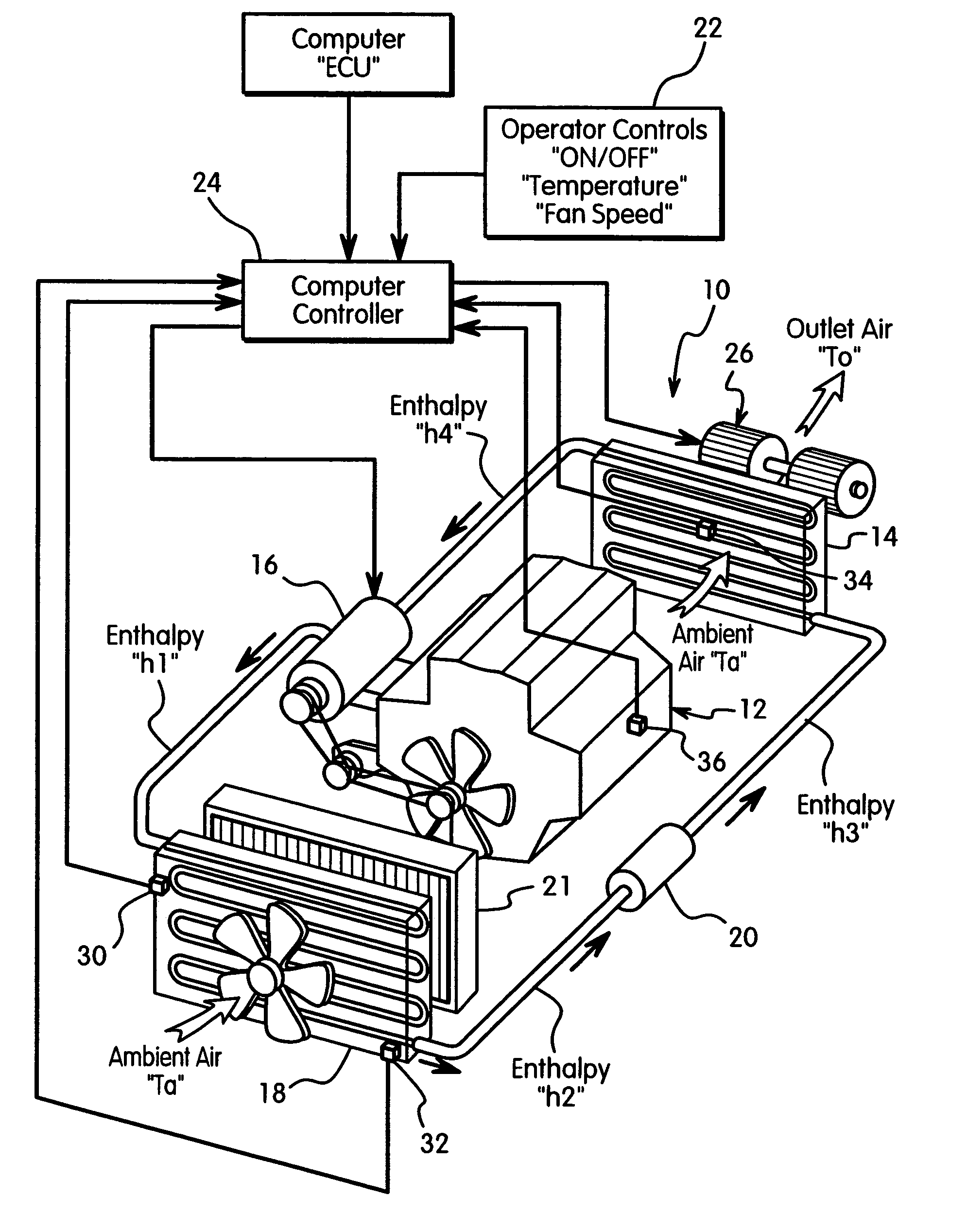
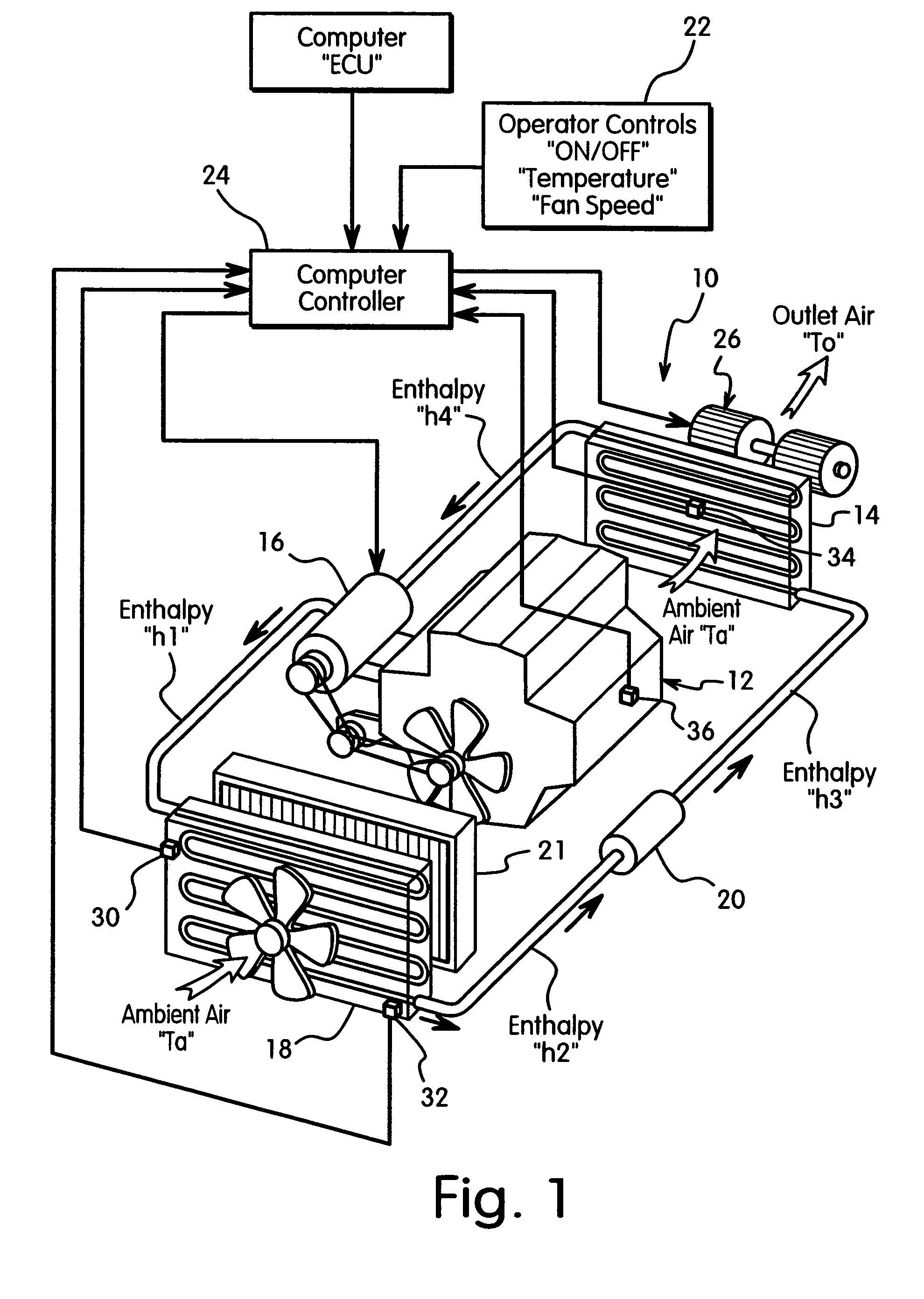
[0028]Referring initially to FIG. 1, an air conditioner 10 is illustrated in accordance with a first embodiment of the present invention. The air conditioner 10 according to the present invention is particularly suitable for an automobile or other passenger vehicle (such as but not limited to a car, an SUV, a minivan, a station wagon, a pick-up truck, etc.,) as well as refrigeration systems for homes and industrial use. In the illustrated embodiment, the air conditioner 10 is driven by a vehicle engine 12 in a conventional manner. Basically, the air conditioner 10 has a refrigerant circuit that inc...


PUM


Abstract

An air conditioner has a controller that controls the operation of a refrigerant circuit that has a compressor, a condenser, an expansion valve or orifice tube, and an evaporator. The condenser receives a compressed refrigerant from the compressor and condenses the refrigerant to either a liquid phase or a saturated liquid-vapor phase. The condensed refrigerant is then passed through the expansion valve or orifice tube to expand the refrigerant and to delivery the refrigerant to the evaporator. The controller is operatively coupled to the compressor to operate the compressor to change an average condenser temperature of the condenser from a first temperature to a second temperature that is lower than the first temperature based on at least one control signal indicative of thermal requirements of a vehicle component influenced by the average condenser temperature of the condenser.

Description

BACKGROUND OF THE INVENTION[0001]1. Field of the Invention[0002]The present invention generally relates to controlling an air conditioner to manage the thermal effect of the condenser preheating air that is used to cool the engine or other components of the vehicle. In other words, the present invention relates to control of an air conditioner such that the performance of the air conditioner is reduced in response to increases in the thermal condition of the engine or other components of the vehicle affected by the condenser temperature.[0003]2. Background Information[0004]A typical automobile air conditioner includes a compressor, a condenser, an expansion valve or orifice tube, and an evaporator. The compressor compresses a cool vapor-phase refrigerant (e.g., Freon, R134a) to heat the same, resulting in a hot, high-pressure vapor-phase refrigerant. This hot vapor-phase refrigerant runs through a condenser, typically a coil that dissipates heat. The condenser condenses the hot vapo...

Claims


Application Information

Patent Timeline
Patent Type & Authority Patents(United States)
IPC IPC(8): F25B1/00B60H1/32F25B49/00
CPCB60H1/3208F25B49/022B60H2001/3251B60H2001/3258B60H2001/3263B60H2001/3266F25B2700/21163F25B2600/112F25B2700/195F25B2700/2106F25B2700/21162B60H2001/327
Inventor EISENHOUR, RONALD
Owner NISSAN MOTOR CO LTD
Learn More