Method for laying a rehabilitating pipe

a rehabilitating pipe and pipe technology, applied in the direction of sewer pipelines, shaft equipment, instruments, etc., can solve the problems of affecting the work efficiency of workers, affecting the efficiency of workers, and the rehabilitating pipe unfortunately floats above the aforementioned position, so as to prevent the deformation of the rehabilitating pipe, reduce the thickness, weight, and the effect of reducing the cost of the segments

Inactive Publication Date: 2007-01-23
SHONAN GOSEI JUSHI SEISAKUSHO KK
View PDF12 Cites 26 Cited by
  • Summary
  • Abstract
  • Description
  • Claims
  • Application Information

AI Technical Summary

Benefits of technology

[0010]The method of the present invention can prevent deformation of the rehabilitating pipe due to its own weight and the weight of the filler, and can prevent the floating up of the rehabilitating pipe when filling with the filler because the rehabilitating pipe being assembled is supported during coupling of the segments in the longitudinal direction by the supporting members, which are previously fixed to the inner wall surface of the existing pipe. Accordingly, superior effects are obtained in that the thickness, weight, and cost of the segments are reduced; in addition, the work of laying the rehabilitating pipe can be performed more simply and in a shorter period of time because it suffices to just fix the supporting members to the inner wall surface of the existing pipe beforehand, and it is unnecessary to accessorily provide steel reinforcing rods for reinforcement or to install supports to prevent deformation.

Problems solved by technology

Due to its own weight and the weight of the filler filled after assembly, the assembled rehabilitating pipe unfortunately deforms into a distorted shape so that it breaks in the downward direction if left as is.
In addition, at a position where the outer periphery of the lower end of the rehabilitating pipe contacts the bottom of the existing pipe, it is necessary to position the center of the rehabilitating pipe so that it is directly below the center of the existing pipe; however, because the specific gravity of the rehabilitating pipe is less than that of the filler, the rehabilitating pipe unfortunately floats above the aforementioned position if left as is.
If the segments are made thicker, then there is a problem in that the weight of the segments increase, thus increasing the burden on the workers performing the assembly of the rehabilitating pipe; in addition, the amount of resin filled in the segments also increases, thus unfortunately leading to a cost increase.
In addition, there is a problem in that the work involved in the method of accessorily providing steel reinforcing rods in a ring shape is extremely troublesome and time consuming.
In addition, there is also a problem in that, in the method of installing the supports, the supports hinder the workers who move inside the narrow rehabilitating pipe when performing the work of filling with the filler, thus degrading working efficiency; in addition, it is necessary to perform the work of removing the supports after hardening of the filler.
In addition, the deformation of the rehabilitating pipe cannot be prevented just with the method that presses down on the upward rise of the rehabilitating pipe with spacers, and it is consequently unfortunately necessary to also use, in parallel, one of the aforementioned methods of preventing deformation.

Method used


Image

  • Method for laying a rehabilitating pipe
  • Method for laying a rehabilitating pipe
  • Method for laying a rehabilitating pipe

Examples


Embodiment Construction

[0019]The present invention will be described based on preferred embodiments, referring to the drawings in which a round rehabilitating pipe is shown whose cross sectional shape orthogonal to the longitudinal direction is round; however, it is understood that the method of the present invention can also be applied even to the laying of a rehabilitating pipe having another shape, such as a rectangle.

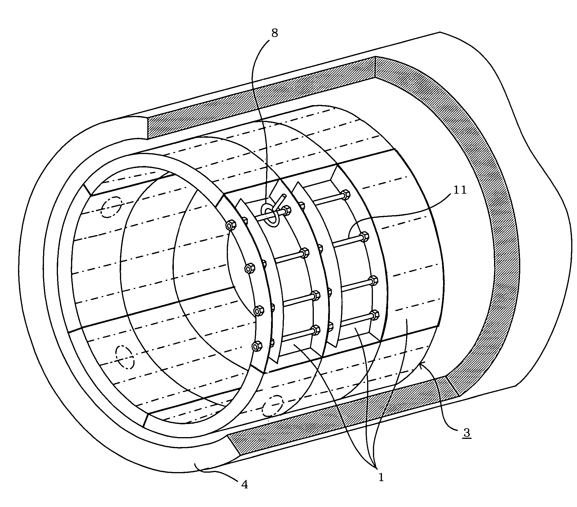
[0020]An existing pipe 4 such as a round sewer pipe is rehabilitated using a rehabilitating pipe 3 whose outer diameter is a prescribed amount less than the inner diameter of the existing pipe 4, as shown in FIG. 5. The rehabilitating pipe 3 is laid inside the existing pipe 4 by coupling segments 1 in the circumferential and longitudinal directions of the existing pipe 4.

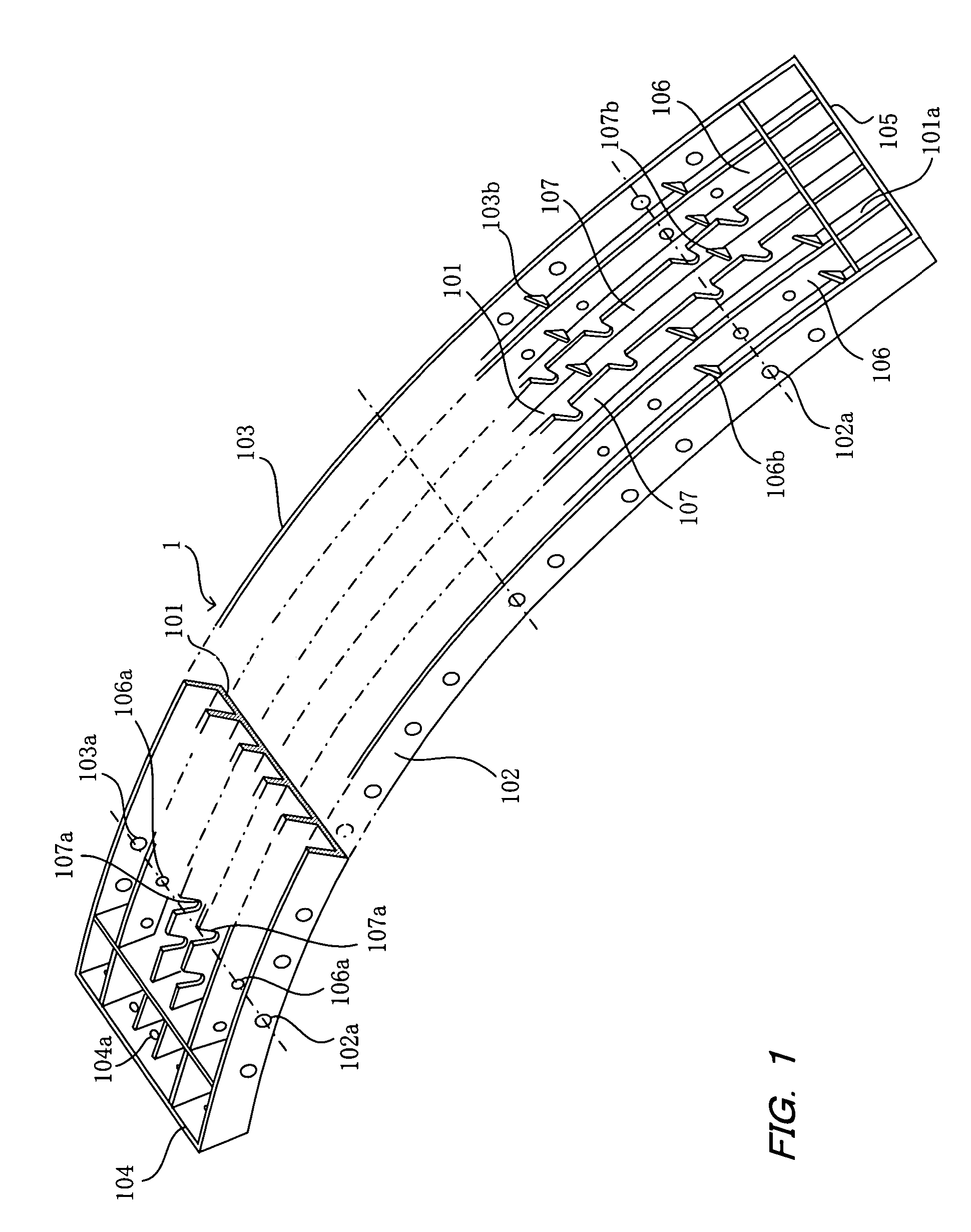
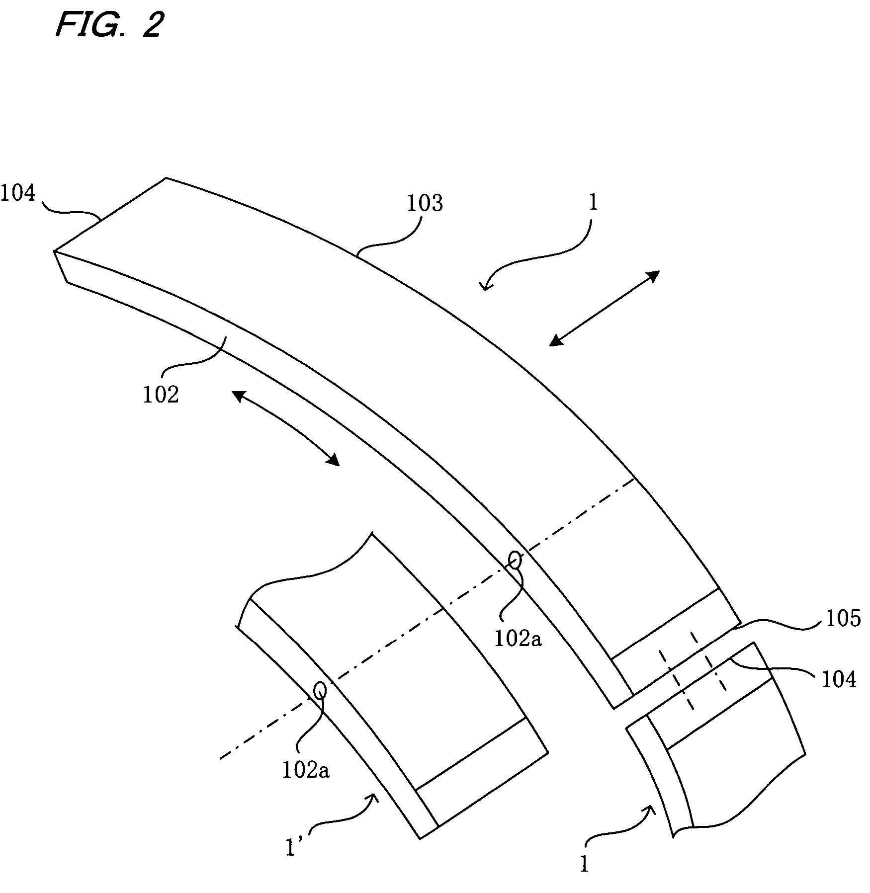
[0021]One segment 1 serves as an assembly unit for the rehabilitating pipe 3 and, as shown in FIG. 1, comprises an inner plate 101, side plates 102 and 103, end plates 104 and 105, and respectively two each of reinforcing...


PUM


Abstract

A rehabilitating pipe is laid inside an existing pipe to rehabilitate the existing pipe. Support members are intergrally connected to an inner wall surface of the existing pipe so that loop portions of the respective support members extend from the inner wall surface of the existing pipe. The rehabilitating pipe is assembled inside of the existing pipe by mutually coupling segments of the rehabilitating pipe in a longitudinal direction of the existing pipe by inserting coupling members through connecting through-holes of the segments and through the loop portions of the respective support members to thereby support the assembled rehabilitating pipe so that the rehabilitating pipe remains inside of the existing pipe after assembly to rehabilitate the existing pipe.

Description

BACKGROUND OF THE INVENTION[0001]1. Field of the Invention[0002]The present invention relates to a method for laying a rehabilitating pipe wherein a rehabilitating pipe is laid inside an existing pipe such as a sewer pipe to rehabilitate the existing pipe.[0003]2. Description of the Prior Art[0004]A method of rehabilitating an existing pipe is known, for example, from Japanese Patent Laid Open Publication No. 2003-286742 in which an existing pipe such as a sewer pipe is rehabilitated using a rehabilitating pipe whose outer diameter is slightly less than the inner diameter of the existing pipe. A filler is filled and hardened in a gap between the outer periphery of the rehabilitating pipe and the inner wall surface of the existing pipe to construct a compound pipe comprising the rehabilitating pipe, the filler, and the existing pipe. The rehabilitating pipe is assembled by coupling segments in the circumferential direction and the longitudinal direction of the pipe. One segment corre...

Claims


Application Information

Patent Timeline
Patent Type & Authority Patents(United States)
IPC IPC(8): F16L55/16E03F7/00E03F3/04E03F3/06F16L1/00F16L55/165
CPCE03F3/06F16L55/1657E03F2003/065A44B15/00G10L15/00
Inventor KAMIYAMA, TAKAOKANETA, KOJIFUJII, KENJIHASEGAWA, TAKESHI
Owner SHONAN GOSEI JUSHI SEISAKUSHO KK
Why Eureka
Try Eureka