Temperature sensing device for metering fluids

a temperature sensing device and fluid technology, applied in the direction of instruments, heat measurement, volume/mass flow by differential pressure, etc., can solve the problems of inaccurate temperature measurement of flowing medium, substantial monetary sums being paid or not paid for delivered gas, inaccurate calculation of flow volume by the meter which includes a computer processing unit (cpu), etc., to improve the rate of temperature transfer, improve the temperature conductivity, and improve the effect of surface area

Inactive Publication Date: 2007-01-23
PARKER INTANGIBLES LLC
View PDF12 Cites 28 Cited by
  • Summary
  • Abstract
  • Description
  • Claims
  • Application Information

AI Technical Summary

Benefits of technology

[0008]The present invention is directed to a thermowell assembly extending within a metallic fluid conduit in a direction perpendicular to the direction of flow to a position past the axial centerline of the metallic conduit. The thermowell assembly includes a temperature sensing probe received within an outer metallic sheath or closed tube. The outer metallic tube which has a closed inner end is exposed to the fluid flowing through the conduit and a plurality of spaced annular ribs or fins extend within the conduit about the outer periphery of the tube for improved temperature conductivity to the temperature sensing probe. The relatively large surface area of the fins improves the rate of temperature transfer by the fins.
[0010]One embodiment of the temperature sensing probe comprises a TSP and tube of a cylindrical cross section with an annular space formed therebetween of a relatively small width or thickness. The annular space adjacent the fins of the thermowell assembly is filled with a temperature conductive liquid for improved temperature conductivity between the outer peripheral surface of the TSP and the adjacent inner peripheral surface of the thermowell assembly. The annular space above the annular fins is filled with air which acts to thermally insulate the TSP from the thermowell assembly.
[0011]The metallic mounting structure for the thermowell assembly has a lower externally threaded metal housing for mounting the thermowell assembly onto the metallic conduit. The metal conduit or pipe has an internally threaded metal cap thereon and the lower metal housing is threaded onto the metal cap. Thermal insulating members in many embodiments, such as thermoplastic fittings or members, are positioned between the metal tube and adjacent metallic mounting members so that no metal to metal contact is provided against the tube thereby minimizing thermal increase or loss from the metal tube. As a result, a highly accurate temperature sensing device has been provided.
[0013]Another embodiment of the temperature sensing probe comprises a temperature sensing assembly mounted within the lower end portion of the internal bore of a finned tube which forms a thermowell within the conduit. The TSP is inserted within the thermowell and held therein by mechanical screw threads through or by a compressive force acting against the TSP. The TSP includes an outer carrier formed of a highly thermal conductive material and a temperature sensing element secured within the carrier by an epoxy material about the sensing element and about a wire connection to the sensing element. Fins on the thermowell tube have an outer diameter slightly less than the diameter of the opening in the conduit wall receiving the thermowell assembly. The thermowell may be fabricated with a uniform stainless steel body, as explained subsequently, for both reducing manufacturing costs and providing even higher accuracy measurements due to the reflective surface of the stainless steel body.

Problems solved by technology

If the temperature of the fluid medium is not correct, the calculated flow volume by the meter which includes a computer processing unit (CPU) will be inaccurate.
In measuring the gas flow through a gas pipeline, for example, in which the gas flow volume is utilized to effect payment of gas being purchased, an inaccuracy in the temperature of the flowing gas may result in substantial monetary sums being paid or not being paid for delivered gas resulting from an error in the temperature of the flowing gas.
Variations in temperature of the exposed pipeline sections results in a temperature conduction from the metallic pipeline to the metallic thermowell assembly which may result in an inaccurate temperature measurement of the flowing medium.
Thus, temperature from the pipe exposed to ambient conditions is conducted to the outer tube of the thermowell which may result in an error in the temperature of the fluid flow under certain conditions.

Method used


Image

  • Temperature sensing device for metering fluids
  • Temperature sensing device for metering fluids
  • Temperature sensing device for metering fluids

Examples


embodiment

of FIG. 16

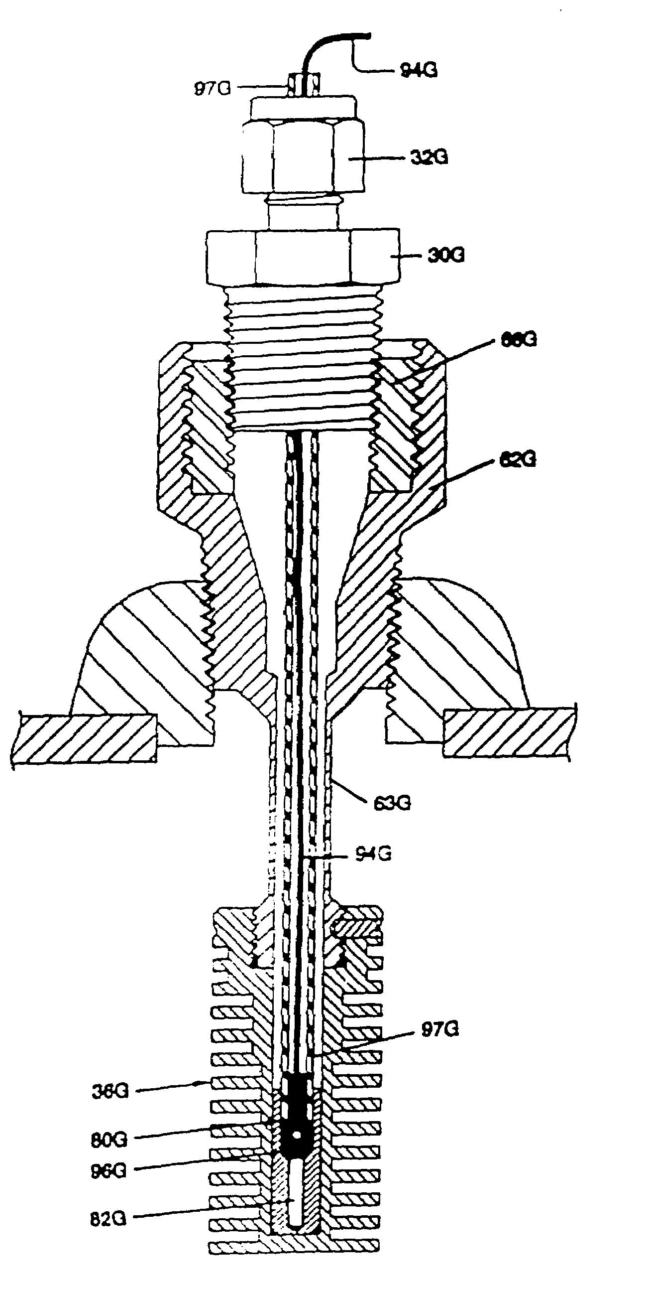
[0073]The FIG. 10 and 12 embodiments utilize the principal of choking down the flow of heat and cold from an “external influence” (cold or hot pipe) toward the sensing section of the thermowell by minimizing the cross section of the thermowell wall that connects the sensing section to the pipe mounting section and using a material with a very low thermal conductivity for this component of the structure. These embodiments further teach constructing the sensing section out of a material with high thermal conductivity that is able to withstand the abrasive and corrosive pipeline environment (e.g., hard anodized aluminum) and increasing the surface area of that section by providing fins. This two piece construction when properly fastened will provide increased accuracy of the flowing gas temperature measurement.

[0074]The thin walled sections lend themselves only to use in situations where the flowing gas is of relatively low velocity. While larger wall section and stabilized v...


PUM

PropertyMeasurementUnit
pressureaaaaaaaaaa
thicknessaaaaaaaaaa
thicknessaaaaaaaaaa

Abstract

A thermowell assembly (20) shown in FIG. 2 is positioned in a pipeline (10) for sensing the temperature of the fluid medium in the pipeline (10) for transmitting the sensed temperature to a meter (12). A temperature sensing probe is received within a temperature conducting tube (36) forming a thermowell and having a plurality of annular fins (40) extending thereabout. In the embodiments of FIGS. 1–7, a liquid (50) is provided in an annular space between the thermocouple (28) and the temperature conducting tube (36). Non-metallic members (70, 74, 80) are positioned between the pipeline (10) and the temperature transmitting tube (36) to isolate thermocouple (28) from ambient changes in the temperature of metal pipeline (10) which may result in an error in the temperature of the flow medium sensed by the thermowell assembly (20). High temperature embodiments shown in FIGS. 4 and 5 do not contain any non-metal components and provide a minimal metal to metal contact between the metallic temperature conducting tube (36B) of the thermowell (20B) and the adjacent metal mounting structure (52B, 62B). The embodiments shown in FIGS. 8–12 illustrate a temperature sensing probe comprising a temperature sensing assembly (80F, 80G) mounted within the internal bore (37F, 37G) of the finned tube (36F, 36G). The temperature sensing assembly (80F, 80G) includes a carrier (82F, 81G) with epoxy (96F, 96G) mounting a temperature sensing element (93F, 82G) within the carrier (82F, 81G).

Description

REFERENCE TO RELATED APPLICATION [0001]This application is a divisional of U.S. Ser. No. 09 / 721,591 filed 22 Nov. 2000, now U.S. Pat. No. 6,390,670, which is a continuation-in-part of U.S. Ser. No. 09 / 546,498 filed 11 Apr. 2000, which is in turn a continuation-in-part of U.S. Ser. No. 09 / 374,126 filed 6 Aug. 1999.FIELD OF THE INVENTION[0002]This invention relates generally to a temperature sensing device for metering fluids, and more particularly to a temperature sensing device or thermowell positioned within a conduit for a flowing fluid medium in which the volume of flow is being metered or measured.BACKGROUND OF THE INVENTION [0003]In fluid metering, the temperature of the flowing medium is an important element or parameter in determining accurately the volume of flow. Normally the conduit includes an orifice through which the fluid medium flows and a suitable fluid meter measures the fluid pressure on opposed sides of the orifice. Flow velocity, line pressure and temperature are...

Claims


Application Information

Patent Timeline
Patent Type & Authority Patents(United States)
IPC IPC(8): G01K1/14G01K13/00G01K7/00C08L79/08G01K1/08G01K13/02G03G15/16
CPCC08L79/08G01F1/36G03G15/1605G01K1/08G01K13/02G01F15/02
Inventor NIMBERGER, SPENCER M.CESSAC, KEVIN J.
Owner PARKER INTANGIBLES LLC
Why Eureka
Try Eureka