
Guide roller assembly for a continuous casting plant

a continuous casting plant and roller technology, applied in the direction of bearing unit rigid support, bearing cooling, sliding contact bearings, etc., can solve the problems of shock loads and increase achieve the effects of increasing the play between the components, reducing material damage, and increasing operational durability

Inactive Publication Date: 2007-01-23
SMS DEMAG AG
View PDF12 Cites 4 Cited by
  • Summary
  • Abstract
  • Description
  • Claims
  • Application Information

AI Technical Summary

Benefits of technology

"The present invention provides a guide roller assembly with a ring-shaped, segmented slide bearing that supports the roller body. This design provides a most durable and resistant support of the guide roller against shocks and soiling. The slide bearing is formlockingly engaged with the roller body and a lubricant or pressurized fluid is introduced between the effective surfaces to reduce friction. The slide bearing is easily mounted and dismounted about the roller body and a seal is provided to prevent leakage. The ring-shaped segmented slide bearing is positioned in the middle of the roller body to provide a shock-resistant and soiling-resistant support. The advantages of the invention include good formlocking engagement, reliable protection against impurities, high soling resistance, and long operational durability even in an extremely contaminated atmosphere. The invention is simple to mount and dismount and provides a high quality sliding support of the roller body."

Problems solved by technology

The use of the slide bearing permitted to reduce damage of the material caused by soiling which, on one hand, contributes to wear and, on the other hand, increases the play between the component and, thus, the shock loads.

Method used


Image

  • Guide roller assembly for a continuous casting plant
  • Guide roller assembly for a continuous casting plant
  • Guide roller assembly for a continuous casting plant

Examples


Embodiment Construction

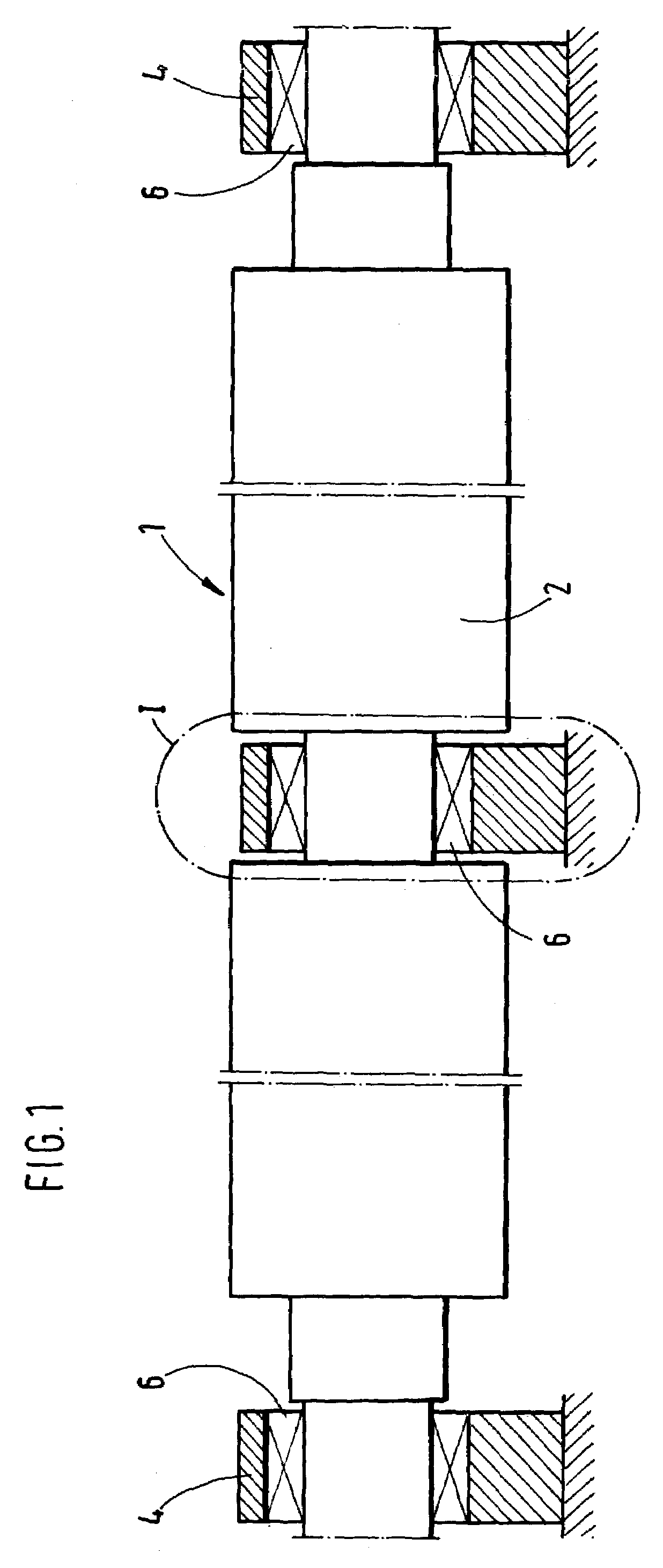
[0016]A guide roller 1 according to the present invention, which is shown in FIG. 1, has a roller body 2 concentrically surrounded by a roller shell. Dependent on the type of the guide roller, the roller body and the roller shell can be formed as a one-piece part or be formed as several parts. For supporting the guide roller 1, two bearing 6 are provided at the opposite ends of the guide roller 1 and one bearing 6 is provided in the middle of the longitudinal extent of the guide roller 1. The bearings 6 are located each in a bearing housing 4.

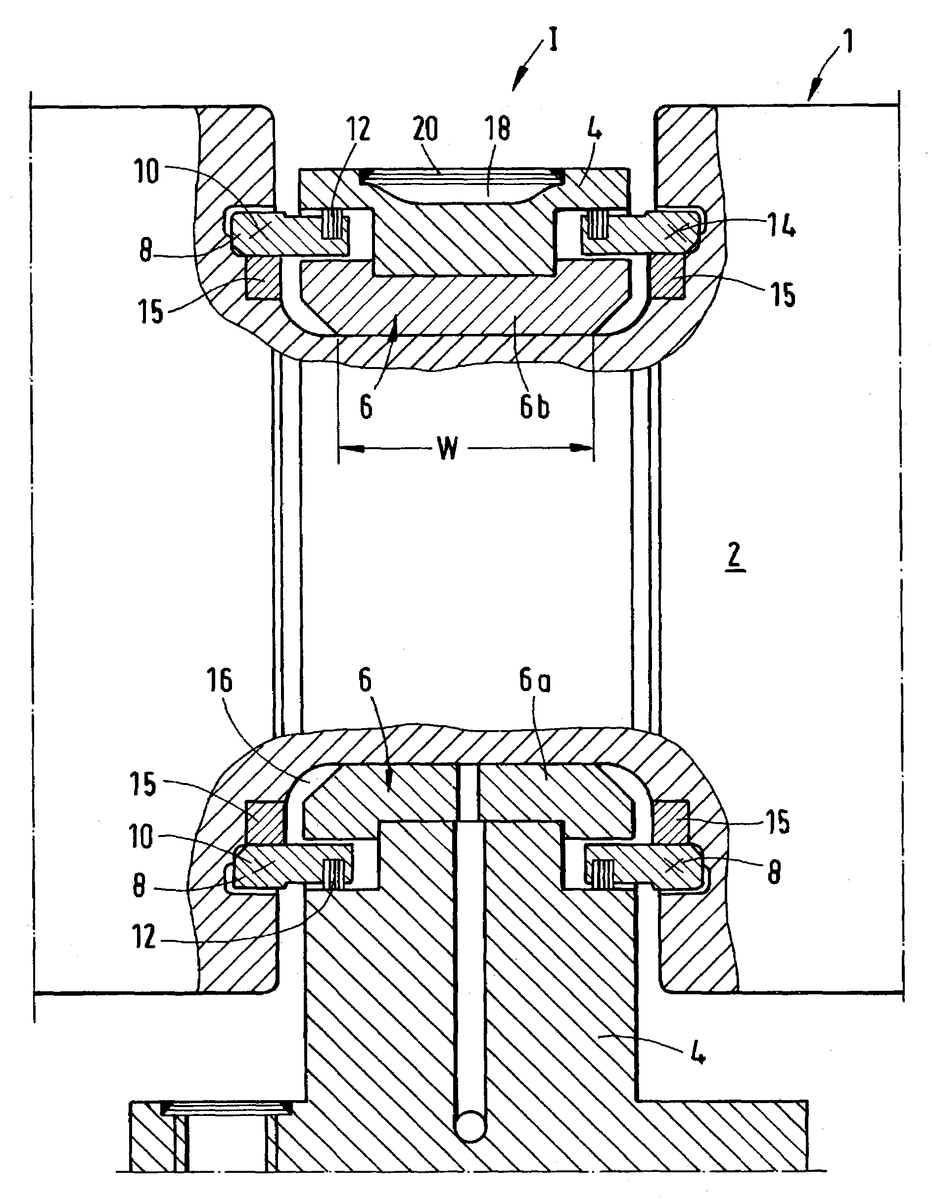
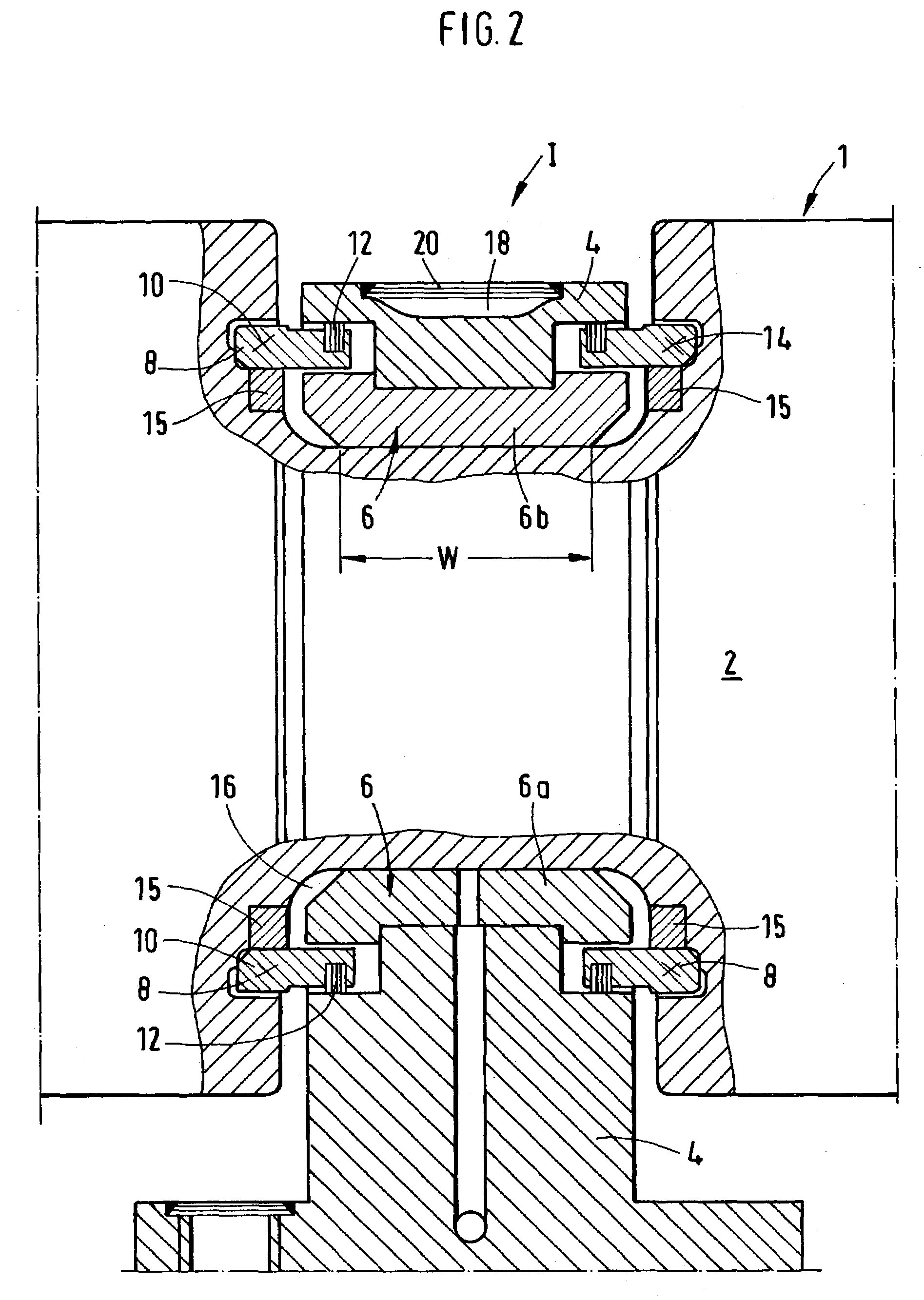
[0017]FIG. 2 show in detail the section I in FIG. 1 which includes the middle bearing 6 which would be described in detail below. To provide for as good as possible insusceptibility to shocks and dirt, the bearing 6 is formed as a ring-shaped, segmented, slide bearing. Advantageously, the bearing 6 is formed of two half-shells 6a and 6b which surround the roller body 2. The two half-shells 6a and 6b of the bearing 6 are connected with each othe...


PUM

PropertyMeasurementUnit
widthaaaaaaaaaa
speedaaaaaaaaaa
mechanical alternatingaaaaaaaaaa

Abstract

A guide roller assembly includes a guide roller and a bearing that supports the roller body of the guide roller and is formed as a ring-shaped, segmented slide bearing.

Description

BACKGROUND OF THE INVENTION[0001]1. Field of the Invention[0002]The present invention relates to a guide roller assembly including a guide roller having a roller body about which a roller shell is concentrically arranged, and a bearing for supporting the roller body.[0003]2. Description of the Prior Art[0004]In continuous casting plants, in addition to guide rollers supported at their opposite ends, guide rollers, which have additional supports, are used. The guide rollers with multiple supports permit to cast strands having an increased width, and at an increased speed. A guide roller with multiple supports is disclosed, e.g., in German Publication DE 197 16 562A1. A guide roller of a continuous casting plant is subjected to high mechanical alternating stresses as a result of a pressure acting on the strand, and to particularly high thermal stresses as a result of its contact with the hot strand. To reduce the thermal stresses, the guide rollers are usually cooled with water. Despi...

Claims


Application Information

Patent Timeline
Patent Type & Authority Patents(United States)
IPC IPC(8): F16C13/02F16C33/74B22D11/128
CPCF16C13/02B22D11/1287F16C2322/00
Inventor GIERTZ, KLAUS
Owner SMS DEMAG AG
Learn More