Flow distributor for PSA vessel

a technology of flow distribution system and psa vessel, which is applied in the direction of separation process, auxillary pretreatment, dispersed particle separation, etc., can solve the problems of adsorbent bed support and flow distribution system being expensive, prone to adsorbent leakage, and increasing the cost of adsorbent bed support and flow distribution system, so as to achieve effective uniform distribution and effective fluid feed distribution

Active Publication Date: 2007-01-23
PRAXAIR TECH INC
View PDF12 Cites 8 Cited by
  • Summary
  • Abstract
  • Description
  • Claims
  • Application Information

AI Technical Summary

Benefits of technology

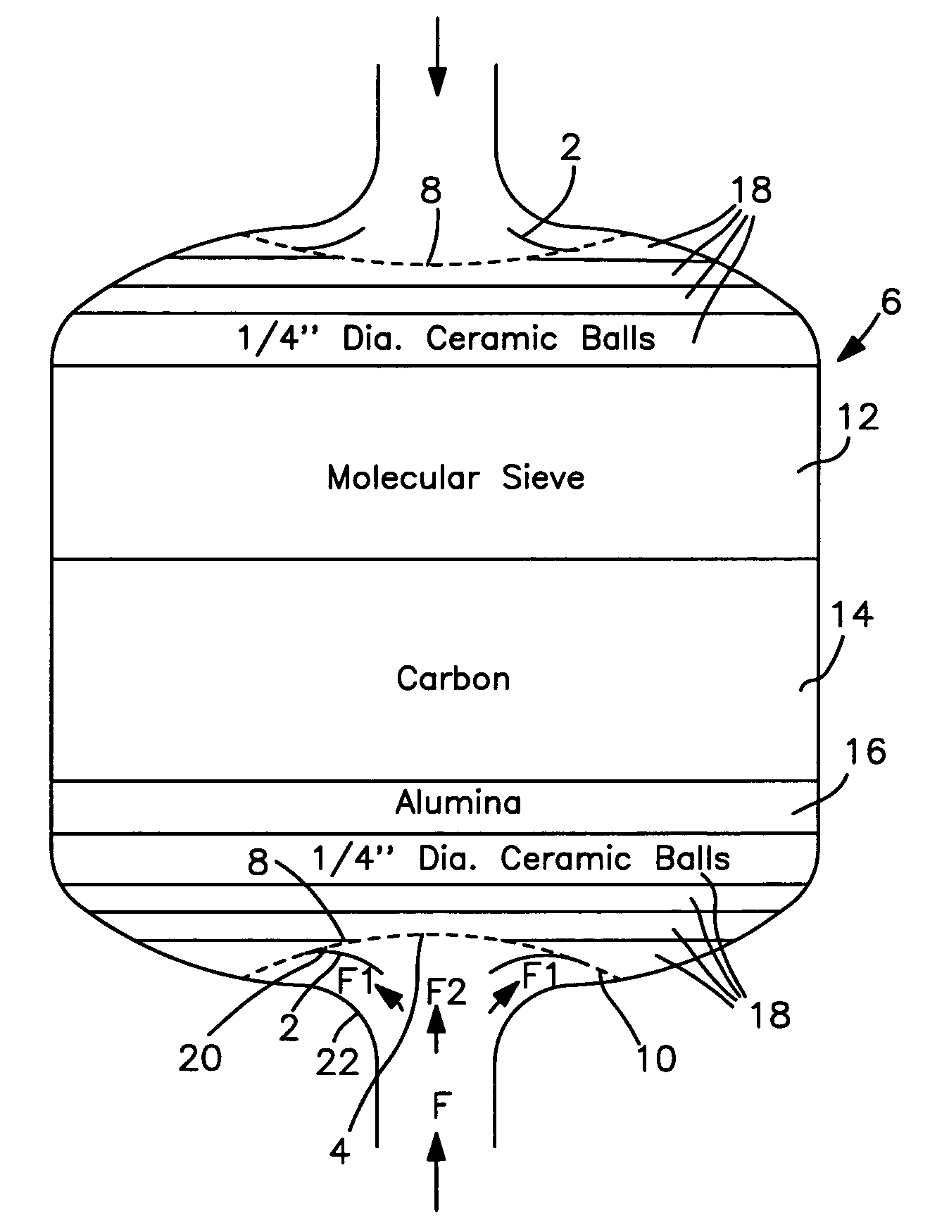
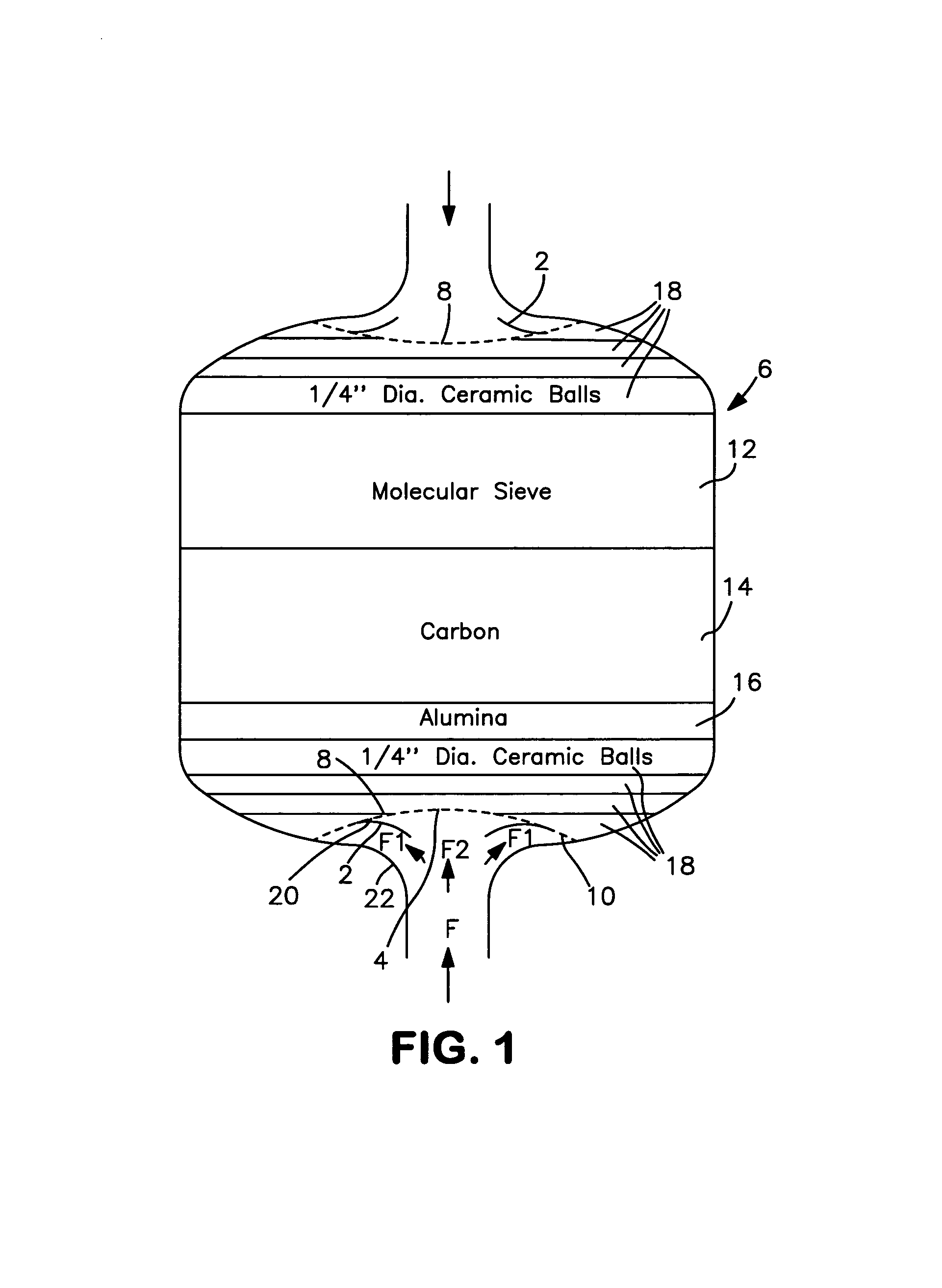
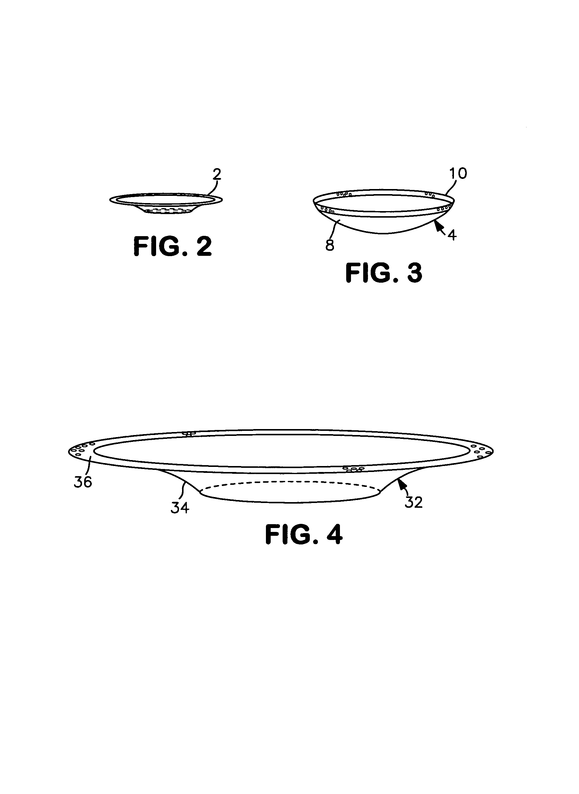
[0022]The present invention relates to an adsorption system for the separation of a more readily adsorbable component of a feed fluid mixture containing said component and a less readily adsorbable component, having at least one adsorption vessel containing a bed of adsorbent material capable of selectively absorbing the more readily absorbable component of said feed fluid mixture, said vessel having a first vessel opening, a second vessel opening at the opposite end and having an inner wall; a deflector funnel having a first funnel opening at one end, a second funnel opening at its opposite end with the second opening larger than the first opening, said first funnel opening extending to form a tapered neck terminating at the second funnel opening, said first funnel opening being juxtaposed one of the vessel openings with the tapered segment being juxtaposed the inner vessel wall adjacent to said vessel opening to provide a channel between the funnel and the inner vessel wall; a perforated cap section disposed to cap the second funnel opening, said perforated cap having at its central area a porosity of less than 10% and at its circumferential area a porosity of about more than 20%, and said funnel / cap arrangement adapted for providing an effectively uniform distribution of a fluid feed to the adsorbent bed.
[0023]Another embodiment of the present invention relates to an adsorption system for the separation of a more readily adsorbable component of a feed fluid mixture containing said component and a less readily adsorbable component, having at least one adsorption vessel containing a bed of adsorbent material capable of selectively absorbing the more readily absorbable component of said fluid gas mixture, said vessel having a first vessel opening, a second vessel opening at the opposite end and having an inner wall; a distribution funnel having an inner wall spaced-apart from an outer wall to provide a fluid channel therebetween and having a first funnel opening at one end and a second funnel opening at its opposite end with the second opening larger than the first opening, the spaced walls having a perforated end at the second funnel opening and an opening end at the first funnel opening so that the spaced-apart walls provides a fluid channel in which the fluid flows from the funnel open end through the perforated funnel end; said first funnel opening extending to form a tapered neck segment terminating at the second funnel opening, said first funnel opening being juxtaposed one of the vessel openings with the tapered segment being adjacent to the vessel inner wall; a perforated cap section disposed to cap the second funnel opening, and said funnel / cap arrangement adapted for providing an effective uniform distribution of a fluid feed to the adsorbent bed.

Problems solved by technology

In addition, large void volumes and pressure drops in the PSA vessel entrance and exit regions, which have adverse effects on the process performance of a PSA system, need to be mitigated in practical commercial operations.
In this regard, those skilled in the art will appreciate that, in PSA systems, e.g. vacuum pressure swing adsorption (VPSA) systems, the adsorbent bed support and the flow distribution system are costly, and become more costly as the diameter of an adsorbent bed increases.
The typical bed support system is also prone to adsorbent leakage if not assembled correctly.
Repair of a leaking bed support system can be costly and time-consuming.
Common bed designs and flow distribution systems that employ bed support plates and associated flow distribution systems, incorporating support ribs, tend to give rise to localized non-uniform gas flow, which results in an undesired penalty in gas separation performance.
The prior art distributors were not able to provide satisfactory flow distributions, with reasonable void volumes.
In fact, they were not responsive to the demands of modern technology.
Flow maldistribution in PSA vessels can cause early breakthrough and loss of efficiency.
Flow maldistributions can also cause sieve movement and local bed fluidization.

Method used


Image

  • Flow distributor for PSA vessel
  • Flow distributor for PSA vessel
  • Flow distributor for PSA vessel

Examples


case 2

[0048]Based on the aforementioned three cases and additional computer simulations, design guidelines were established for flow distributors to be preferably used in all vessel sizes. The design guidelines are as follows:[0049]Case 1—without flow extender, flow maldistribution (high>10%) is unavoidable with d / D[0050]Case 2—without flow extender, acceptable flow maldistribution (less than 10%) is achieved when d / D≧50%.[0051]Case 3—with flow extender, acceptable flow maldistribution (less than 10% ) is achieved when X / D>75%.

[0052]Table 1 gives several examples using the novel flow distributor components to achieve low flow maldistribution.

[0053]

TABLE 1Vessel Specification With and WithoutFlow ExtenderVesselWithoutWithoutWithWithDiameter, DExtenderExtenderExtenderExtenderInchRangeBest ModeRangeBest Mode60d ≧ 30″d = 40″x ≧ 45″x = 50″78d ≧ 39″d = 52″x ≧ 59″x = 65″96d ≧ 48″d = 64″x ≧ 72″x = 80″114d ≧ 57″d = 76″x ≧ 86″x = 95″122d ≧ 61″d = 81″x ≧ 92″x = 102″129d ≧ 65″d = 86″x ≧ 97″x = 107″

[0...


PUM

PropertyMeasurementUnit
porosityaaaaaaaaaa
porosityaaaaaaaaaa
porosityaaaaaaaaaa

Abstract

The present invention is a PSA system having at least one vessel that uses a multi-segmented flow distributor to provide a uniform fluid across the adsorbent bed in the vessel.

Description

BACKGROUND OF THE INVENTION[0001]1. Field of the Invention[0002]The invention relates to pressure swing adsorption gas separation operations. More particularly, it relates to an improved flow distribution system for pressure swing adsorption vessels.[0003]2. Description of the Prior Art[0004]Adsorption processes have been widely used for the separation and purification of gases. In recent years, pressure swing adsorption (PSA) systems have been developed for enhanced gas separation operations, particularly for the commercial production of oxygen and / or nitrogen from air. In the operation of PSA systems, an adsorption-desorption-repressurization processing sequence is employed, with the passage of air or other feed gas mixture at an upper adsorption pressure to an adsorption system for the selective adsorption of a more readily adsorbable component of air or other feed gas mixture by one or more adsorbent beds, and the passage through said bed(s) of a less readily adsorbable componen...

Claims


Application Information

Patent Timeline
Patent Type & Authority Patents(United States)
IPC IPC(8): B01D53/04B01D53/02
CPCB01D53/0431B01D53/047B01D2253/102B01D2253/104B01D2259/4146B01D2253/311B01D2253/34B01D2256/10B01D2256/12B01D2253/106
Inventor BAKSH, MOHAMED SAFDAR ALLIENEU, BERNARD THOMASZADEH, DARIUSH H.
Owner PRAXAIR TECH INC
Why Eureka
Try Eureka