
Automatic control of laser diode current and optical power output

Inactive Publication Date: 2007-01-23
STRATOS INT +1
View PDF3 Cites 29 Cited by
  • Summary
  • Abstract
  • Description
  • Claims
  • Application Information

AI Technical Summary

Benefits of technology

[0011]A first aspect of the invention provides a control system that generates a control signal to control output power. The control system includes a sensor that senses the magnitude of the output power, an operational amplifier (op amp) to compare the sensed output power against a reference signal and adjust the control signal appropriately to

Problems solved by technology

However, providing resistor 140 with these operating characteristics may be prohibitively expensive.
Further, large variations in laser diode and photodiode characteristics, such as output optical energy, wavelength and the like, as well as variations in optical power output requirements according to application or status, result in tradeoffs between the achievable PO adjustment range and resolution for a given resistor 140.
Accordingly, to achieve sufficient dynamic range for calibration, and adequate resolution for temperature compensation, prior art automatic power control systems for laser diodes typically employ one of the following solutions: (1) a one-size-fits-all approach for resistor 140, degrading system performance due to the range versus resolution limitations of potentiometers, or (2) replacing a resistor 140 with several resistors or with dynamically switchable resistors, or adding a second potentiometer, which increases manufacturing complexity and cost.
Further, quantization noise may cause the digital result to vary between two adjacent results when the measured parameter is in between two adjacent results.

Method used


Image

  • Automatic control of laser diode current and optical power output
  • Automatic control of laser diode current and optical power output
  • Automatic control of laser diode current and optical power output

Examples


Embodiment Construction

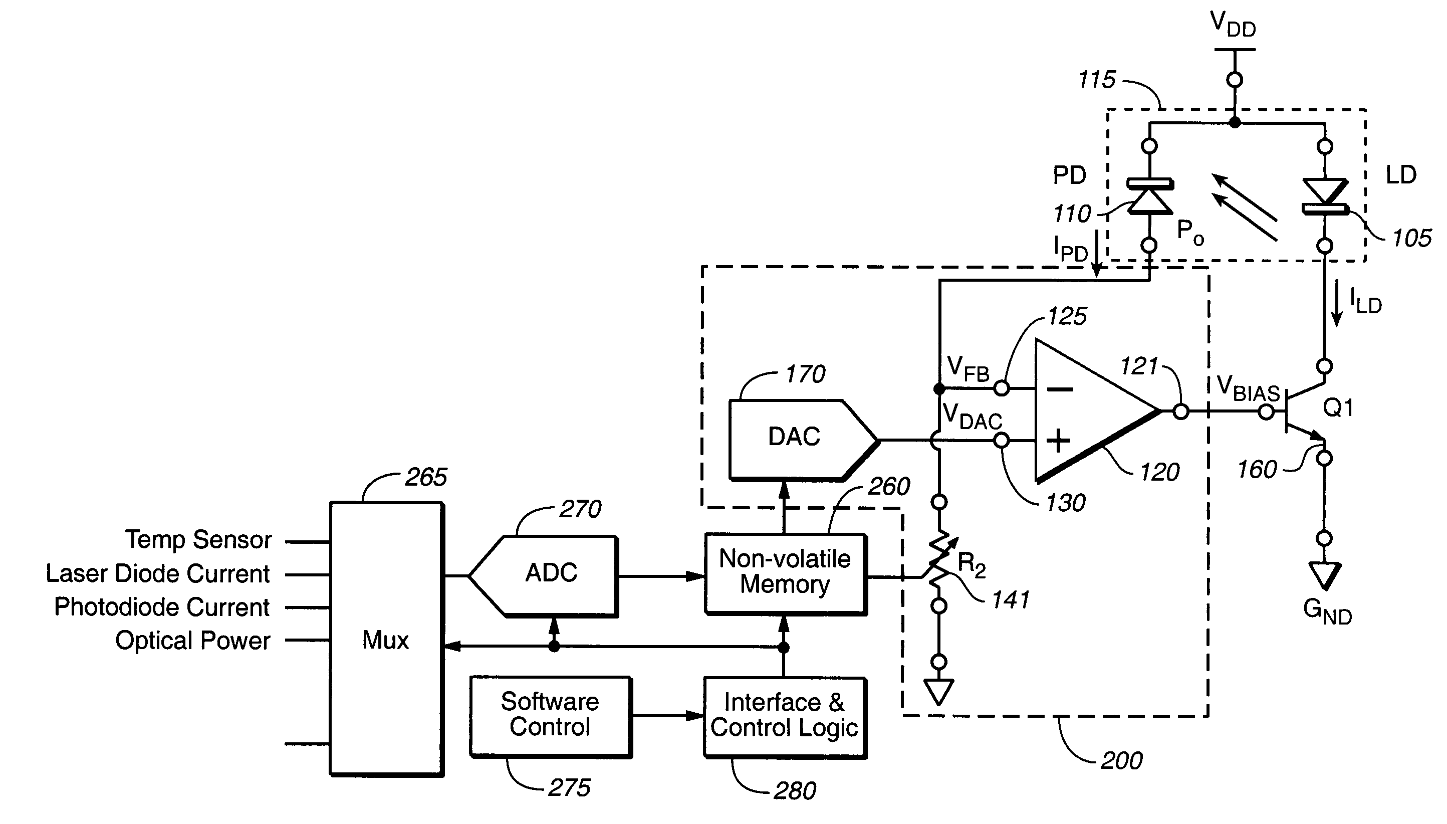
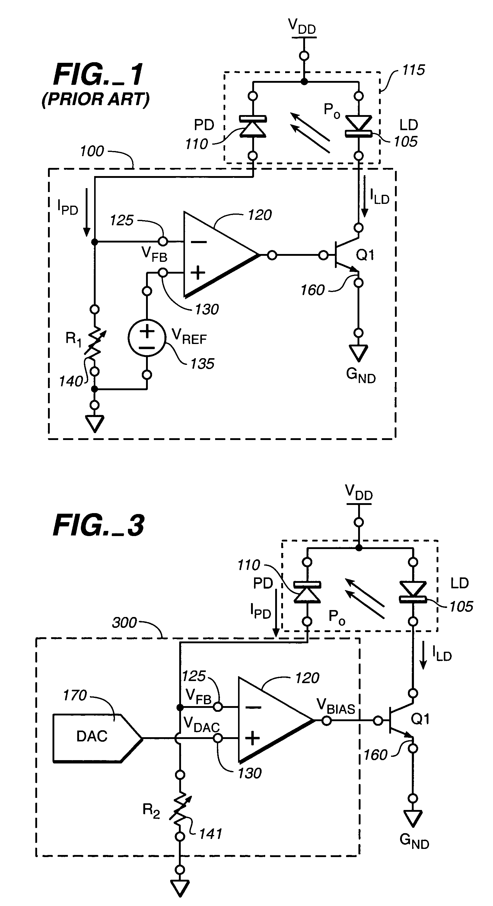
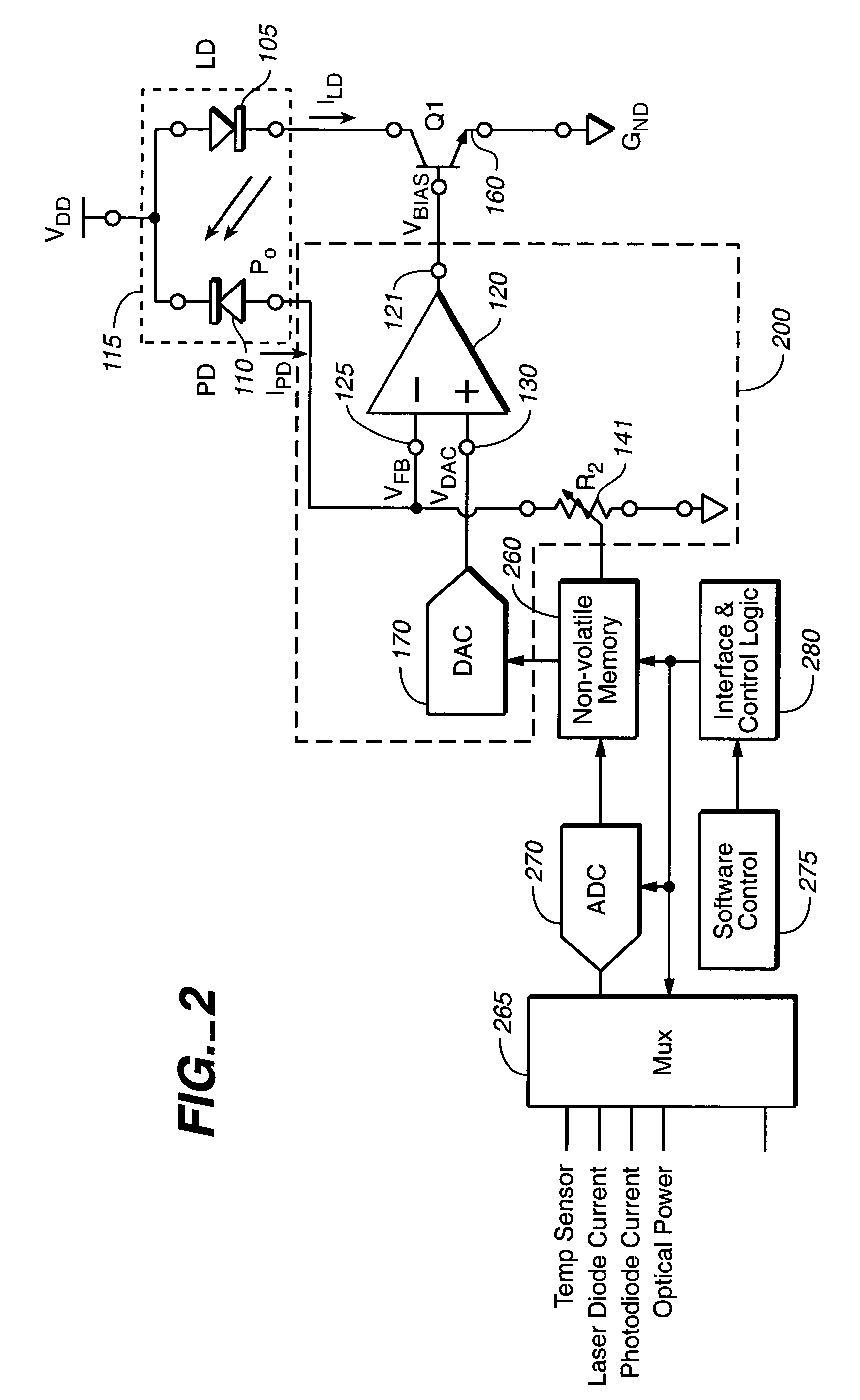
[0024]The present invention provides automatic power control systems to regulate the output power of one or a plurality of laser diodes. In general, a coarse setting of laser diode optical power is provided by a variable resistor, while fine adjustment and compensation is simultaneously provided through the use of a digital-to-analog converter (DAC). Various embodiments of the present invention support common-cathode, common-anode, optical feedback, and current feedback configurations, as well as combinations thereof. Further, each configuration may support non-volatile memory storing configuration, calibration, or temperature compensation information, or the like, for use by the variable resistor and / or DAC.

[0025]In another aspect, systems, methods, and circuit topologies are provided to reduce or substantially remove threshold-sensitive jitter from compensation applied to a system based on a measured parameter such as temperature, age, light level, humidity, altitude, and the like...


PUM


Abstract

An automatic power control system provides a control signal that regulates the output power of at least one laser diode. Coarse adjustment of the control signal is provided by a first means, preferably a digital variable resistor, while fine adjustment and compensation is provided by a second means, preferably by a digital-to-analog converter that receives an input signal proportional to a sensed control system parameter. The control system includes an operational amplifier having a first input coupled to sense output power, and a second input coupled to a DAC to provide finer resolution control. Memory can store system parameter or system parameter variations that can be coupled to the DAC and / or variable resistor to enhance system stability over ambient variations.

Description

FIELD OF THE INVENTION[0001]The present invention relates generally to laser diodes and associated control systems, temperature compensation for such systems, and more particularly to control of laser diode current and optical power output in fiber optic communication systems.BACKGROUND[0002]Laser diodes, also known as an injection lasers or diode lasers, are commonly used in optical fiber systems, communication systems, compact disc players, laser printers, remote-control devices, intrusion systems, and the like to provide coherent radiation in response to applied current.[0003]It is desirable to control the power output of a laser diode with an automatic power control (APC) circuit to enhance reliability and stability. Conventional automatic power control circuit 100 used to control the optical power output (PO) of common-anode laser diode 105 is shown in FIG. 1. The function of control system 100 is to increase the current flowing through laser diode 105, ILD, in response to a de...

Claims


Application Information

Patent Timeline
IPC IPC(8): H01S3/00H01S3/13
CPCH01S5/0683H01S5/0617H01S5/06808H01S5/06804
Inventor KUNST, DAVIDMARTINEZ, STEVENLEWANDOWSKI, ROBERT JAMESCHAMBERS, PETERJUDKINS, III, JOSEPH JAMESTORRES, LUISLINDSAY, TOM
Owner STRATOS INT
Learn More