Eureka AIR delivers breakthrough ideas for toughest innovation challenges, trusted by R&D personnel around the world.

Idle speed controller for internal combustion engine

a technology of internal combustion engine and controller, which is applied in the direction of electric control, machines/engines, output power, etc., can solve the problems of increasing the internal exhaust gas recirculation, misfires, and misfires when the engine is idling, so as to prevent the occurrence of misfires efficiently and effectively

Inactive Publication Date: 2007-01-30
TOYOTA JIDOSHA KK
View PDF4 Cites 10 Cited by
  • Summary
  • Abstract
  • Description
  • Claims
  • Application Information

AI Technical Summary

Benefits of technology

The present invention provides an idle speed controller for internal combustion engines that can prevent misfires when there is a failure in the variable valve timing mechanism. The controller includes an intake and exhaust valve, and a variable valve timing mechanism for adjusting the timing of the valves. The controller uses an electronic control unit to execute idle speed control and increase the target idle speed by adjusting the working angle of the valves. The controller also includes an intake and exhaust variable working angle mechanism for adjusting the working angle of the valves. The invention provides efficient and effective prevention of misfires in the engine and improves idle speed control.

Problems solved by technology

In an internal combustion engine that uses such a variable valve timing mechanism for its intake system, misfires may occur when the engine is idling.
Such misfires occur when the valve timing of the intake valve is advanced from the intended timing.
This increases internal exhaust gas recirculation (EGR) and deteriorates combustion conditions.
Thus, depending on the setting of the valve working angle, when an advancement failure occurs in the variable valve timing mechanism, the increase amount of the internal EGR relative to an increase of valve overlap may change.
In such an internal combustion engine, if the idle-up control is performed in the same manner whenever an advancement failure occurs, the idle-up amount may become excessive or insufficient.
As a result, execution of unnecessary idle-up control may lower the fuel efficiency when the idle-up amount is excessive or cause misfires when the idle-up amount is insufficient.

Method used


Image

  • Idle speed controller for internal combustion engine
  • Idle speed controller for internal combustion engine
  • Idle speed controller for internal combustion engine

Examples


Embodiment Construction

[0021]A preferred embodiment of the present invention will now be described with reference to the drawings.

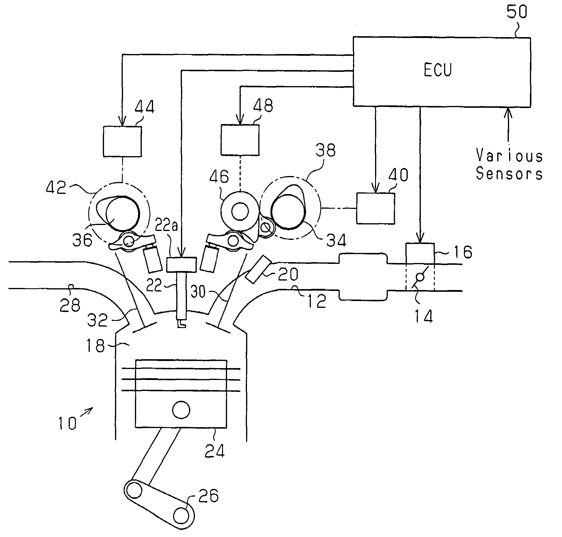
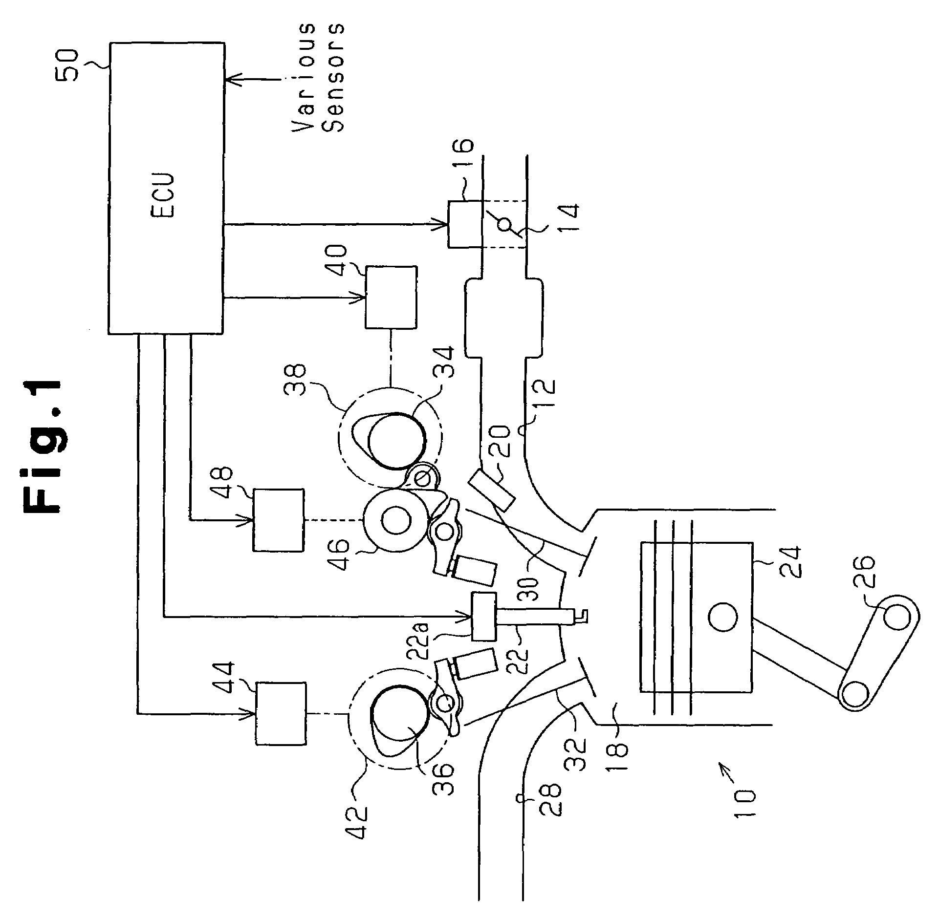
[0022]As shown in FIG. 1, an internal combustion engine 10 includes an intake passage 12 provided with a throttle valve 14. The throttle valve 14 is connected to a throttle motor 16. The throttle motor 16 is driven to adjust the amount the throttle valve 14 is open (throttle open amount TA) and control the amount of air drawn into a combustion chamber 18 through the intake passage 12. The intake passage 12 further includes an injector 20, which injects fuel into the intake passage 12.

[0023]Air-fuel mixture formed by intake air and injected fuel is ignited by an ignition plug 22 in the combustion chamber 18 of the internal combustion engine 10. The ignition timing of the ignition plug 22 is adjusted by an igniter 22a. The ignition burns the air-fuel mixture and reciprocates a piston 24 so as to rotate a crankshaft 26. Subsequent to combustion, the air-fuel mixture is discharged ...


PUM


Abstract

An idle speed controller for an internal combustion engine provided with an intake variable valve timing mechanism for varying valve timing and a variable working angle for varying a valve working angle of an intake valve. The controller performs idle speed control. When an advancement failure occurs in the intake variable valve timing mechanism, the controller performs idle-up control to increase the target idle speed. When the valve working angle of the intake variable working angle mechanism is less than a predetermined value, the electronic control unit changes an increase amount of the target idle speed to a lower value if an advancement failure occurs when performing the idle-up as compared to when the valve working angle is greater than the predetermined value.

Description

BACKGROUND OF THE INVENTION[0001]The present invention relates to an idle speed controller for application in an internal combustion engine provided with a variable valve timing mechanism and a variable working angle mechanism, and more particularly, to an improvement of a control structure for preventing misfires when an angle advancement failure occurs in a variable valve timing mechanism.[0002]In the prior art, a variable valve timing mechanism is used to vary the valve timing of an intake valve and an exhaust valve. The variable valve timing mechanism uses a hydraulic or electric actuator to alter the rotation angle of a camshaft relative to a crankshaft in order to vary the valve timing of an intake valve and an exhaust valve. In an internal combustion engine that uses such a variable valve timing mechanism for its intake system, misfires may occur when the engine is idling. Such misfires occur when the valve timing of the intake valve is advanced from the intended timing. Such...

Claims


Application Information

Patent Timeline
Patent Type & Authority Patents(United States)
IPC IPC(8): F02D41/16F01L1/34
CPCF01L1/34F02D13/0215F02D13/023F02D13/0261F01L1/185F01L13/0063F01L2001/0537F01L2105/00Y02T10/18F01L2800/12F01L2800/00F01L2305/00Y02T10/12
Inventor KATO, TOSHIKAZUFUWA, NAOHIDE
Owner TOYOTA JIDOSHA KK
Why Eureka
Eureka Blog
Learn More