System and method for hermetic seal formation

a hermetic seal and seal technology, applied in the field of hermetic seal formation, can solve the problems of thermal damage, affecting the stability of the resulting seal, and the soldering process may occur too quickly, so as to reduce thermal induced warpage, increase the melting temperature of the hermetic seal, and minimize the effect of thermal induced warpag

Inactive Publication Date: 2007-01-30
AVAGO TECH INT SALES PTE LTD
View PDF14 Cites 63 Cited by
  • Summary
  • Abstract
  • Description
  • Claims
  • Application Information

AI Technical Summary

Benefits of technology

[0006]Although the temperatures of low-melting solders previously mentioned are desirable for forming hermetic seals, there is a need to increase the melting temperatures of the hermetic seals that are formed without sacrificing the advantages that these low-melting solders provide. It is desirable to make a hermetic seal at a relatively low temperature in order to minimize thermal induced warpage. In addition, if the seal is high melting when it is made, then it can be used to engage in subsequent step soldering which is sometimes required in manufacturing operations. By having an increased melting temperature, joint creep resistance may be improved. Also, dimensional stability and optical performance may be improved.

Problems solved by technology

If the reflow time employed is excessively long, then thermal damage may occur.
On the other hand, if the reflow time is excessively short, then the soldering process may occur too rapidly and stability of the resulting seal will be affected.
However, using these other metals might require a longer reflow time to form the hermetic seal due to their different melting points.

Method used


Image

  • System and method for hermetic seal formation
  • System and method for hermetic seal formation
  • System and method for hermetic seal formation

Examples


first embodiment

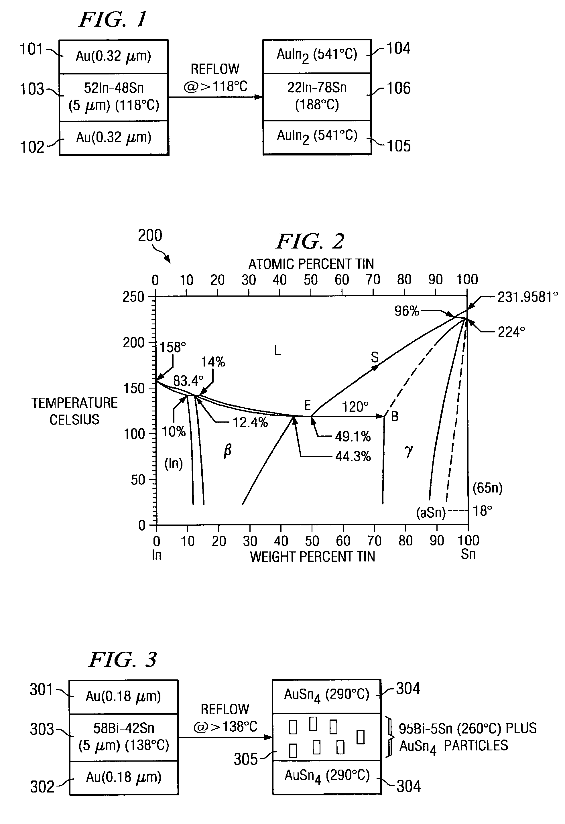
[0025]In the invention, the two surfaces to be sealed are typically coated with at least 0.32 μm of Au 101, 102. 5 μm layer of 52In-48Sn 103 (note that all solder compositions are in weight percent unless specified otherwise) is coated on at least one of the surfaces. Note that all of the solder may be on one surface, or a portion of the solder may be on each surface (e.g. 0.3 μm on one surface and 0.2 μm on the other surface). The two surfaces are typically placed in contact and reflow at a temperature typically approximately 30–40° C. above the melting temperature of eutectic 52In-48Sn (118° C.). The chemical reactions and phase changes that occur during reflow would be best described in the In—Sn—Au phase diagram at 118° C. FIG. 2 approximates the In—Sn—Au diagram with the In—Sn binary phase diagram 200.

[0026]As shown in FIG. 1, AuIn2 is the intermetallic compound 104, 105 formed between Au and molten In—Sn alloys 106. The Sn concentration in AuIn2 is typically negligible. The me...

second embodiment

[0027]In the invention, the two surfaces to be sealed are typically coated with at least 0.18 μm of Au. 5 μm layer of 58Bi-42S n is coated on one of the surfaces. Note that all of the solder may be on one surface, or a portion of the solder may be on each surface (e.g. 0.3 μm on one surface and 0.2 μm on the other surface). The two surfaces are typically placed in contact and reflow at a temperature typically approximately 30–40° C. above the melting temperature of eutectic 58Bi-42Sn (138° C.).

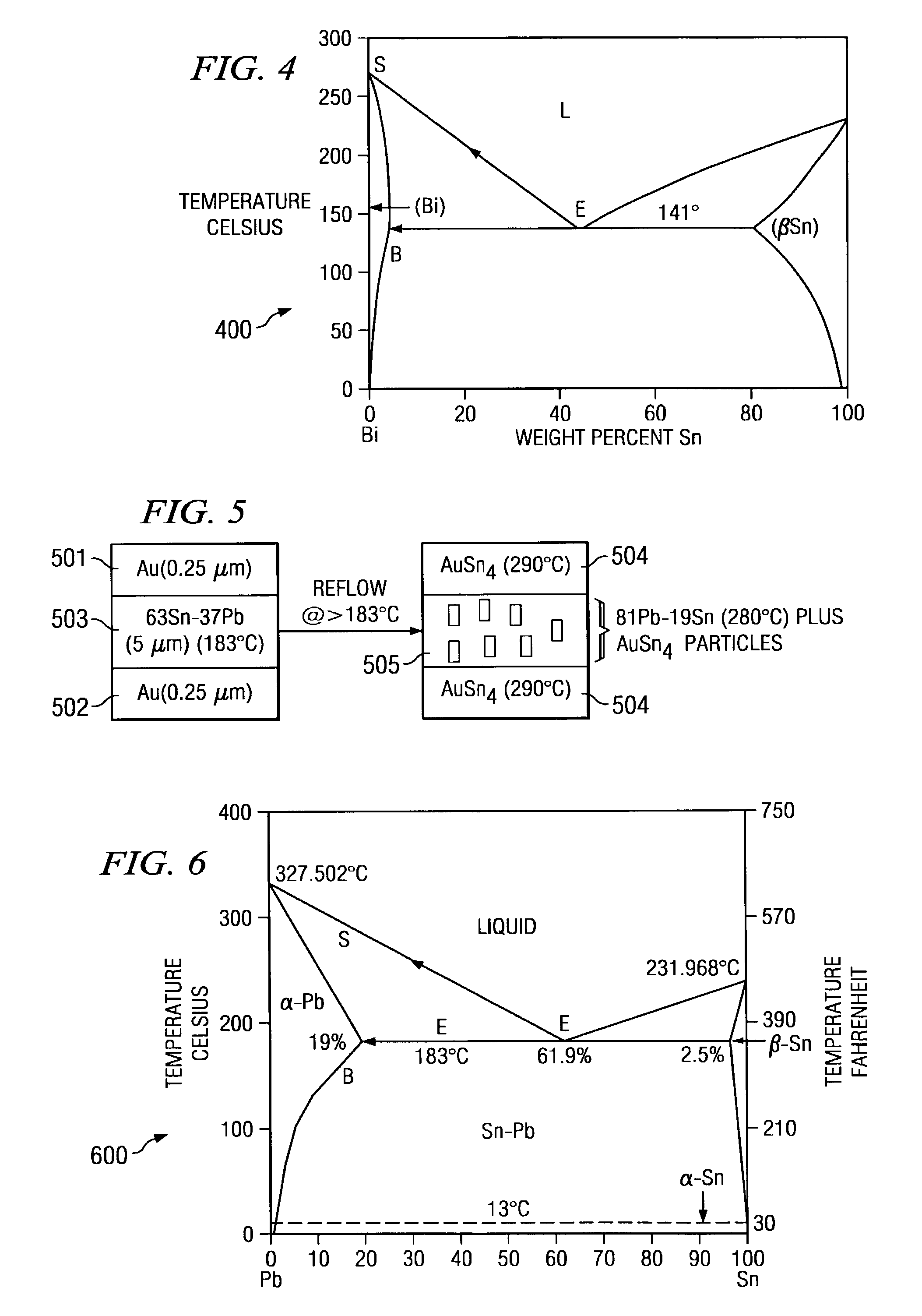
[0028]Similar to the 52In-48Sn solder, as shown in FIG. 3, Au layers 301, 302 react with Sn in molten eutectic 58Bi-42Sn 303, forming the intermetallic compound 304, AuSn4, typically with little reaction between Bi and Au. The melting temperature of this resulting intermetallic compound is 290° C. as obtained from the Sn—Au binary phase diagram. However, unlike with the 52In-48Sn solder, the AuSn4 intermetallic compound forms not only at the Au / molten Bi—Sn interface but also inside the molten...

third embodiment

[0030]In the invention, the two surfaces 501, 503 to be sealed are typically coated with at least 0.25 μm of Au. Note that all of the solder may be on one surface, or a portion of the solder may be on each surface (e.g. 0.3 μm on one surface and 0.2 μm on the other surface). 5 μm layer 503 of 63Sn-37Pb is coated on one of the surfaces. Note that all of the solder may be on one surface, or a portion of the solder may be on each surface (e.g. 0.3 μm on one surface and 0.2 μm on the other surface). The two surfaces are placed in contact and reflow at a temperature typically approximately 30–40° C. above the melting temperature of eutectic 63Sn-37Pb (183° C.).

[0031]As shown in FIG. 5, similar to the Bi—Sn solder above, Au layers react with Sn in molten 63Sn-37Pb, forming the intermetallic compound AuSn4 504, typically with little reaction between Pb and Au. The melting temperature of this resulting intermetallic compound is 290° C. as obtained from the Sn—Pb binary phase diagram in FIG....


PUM

PropertyMeasurementUnit
thicknessaaaaaaaaaa
thicknessaaaaaaaaaa
thicknessaaaaaaaaaa

Abstract

System and method for formation of a hermetic seal with an significantly greater melting temperature than the melting temperature of the solder employed. The hermetic seal is formed from a solder with a low melting point and a metal having a predetermined thickness that corresponds to the solder. The solder and metal combination undergoes reflow for a period of time relative to the solder thickness. The resultant seal has a melting point at a temperature significantly greater than the melting temperature of the solder.

Description

TECHNICAL FIELD[0001]The present invention relates in general to seal formation, and in particular to a system and method for hermetic seal formation.BACKGROUND OF THE INVENTION[0002]Hermetic seals usually are required for optoelectronic devices to make the device impervious to external influences, such as moisture. Low melting solders are desirable for sealing because the low melting temperatures will reduce the thermal induced warpage in these devices. Typical examples of low-melting solders used to form hermetic seals include indium (Tmelt=156° C.), 52In-48Sn (Tmelt=118° C.), 58Bi-42Sn (Tmelt=138° C.), and 63Sn-37Pb (Tmelt=183° C.).[0003]The hermetic seal is produced when the base metal, Au or Cu for example, dissolves into a molten metal, such as Sn or In and their alloys, and the active constituent in the solder combines with the base metal to form an intermetallic compound. The relative amount of base metal that goes into the solution is related to its solubility in the solder...

Claims


Application Information

Patent Timeline
Patent Type & Authority Patents(United States)
IPC IPC(8): B23K31/02B23K1/14B23K35/00B23K35/02B23K35/14B23K35/26B23K35/30C22C11/06C22C12/00C22C28/00
CPCB23K35/001B23K35/0222B23K35/26H01L2224/83825B23K35/268B23K35/3013B23K2201/36B23K35/264H01L2924/00011B23K2101/36H01L2224/83205
Inventor MEI, ZEQUN
Owner AVAGO TECH INT SALES PTE LTD
Why Eureka
Try Eureka