Vehicle door mirror device

a rearview mirror and mirror technology, applied in the direction of mirrors, mountings, instruments, etc., can solve the problem of restricting the turning of the housing in one direction around the shaft, and achieve the effect of reducing the cost of the housing

Inactive Publication Date: 2007-01-30
KK TOKAI RIKA DENKI SEISAKUSHO
View PDF3 Cites 4 Cited by
  • Summary
  • Abstract
  • Description
  • Claims
  • Application Information

AI Technical Summary

Benefits of technology

[0014]The present invention was made in order to obtain a vehicle door mirror device with which the types of parts used therein can be reduced.
[0023]Due to this arrangement, when compared to a structure where the restricting component directly rubs against or comes into contact with the housing, abrasion and the like is less likely to occur.
[0024]Further, in the above-described embodiment, the restricting unit can be formed at the stand or the stay parallel to the shaft and inserted into a groove portion formed in the bottom portion of the housing in a state where the housing is supported by the shaft. The restricting unit can restrict the turning of the housing in the other direction around the shaft by coming into contact with an inner wall of the groove portion at the second turning position.
[0027]The housing turns around the shaft due to each of the protrusions entering the inner sides of the respective multiple depressions. When the housing reaches the first turning position, one of the protrusions comes into contact with the wall facing the peripheral direction of the ring component formed towards the inner sides of the depressions of the ring component, thereby restricting the turning of the housing.
[0032]Due to this, displacement of the restricting component around the shaft relative to the stand or stay is limited by the limiting portions, and position placement of the restricting component is achieved.
[0034]With the vehicle door mirror device of the present invention, the same restricting component can be applied without changing the structure of the restricting component even if the angle of rotation specifications of the main body of the mirror device differ, whereby both the types of parts and the cost thereof can be reduced.

Problems solved by technology

Due to this impeding of the ring component by the restricting component, turning of the housing in the one direction around the shaft is restricted.

Method used


Image

  • Vehicle door mirror device
  • Vehicle door mirror device
  • Vehicle door mirror device

Examples


Embodiment Construction

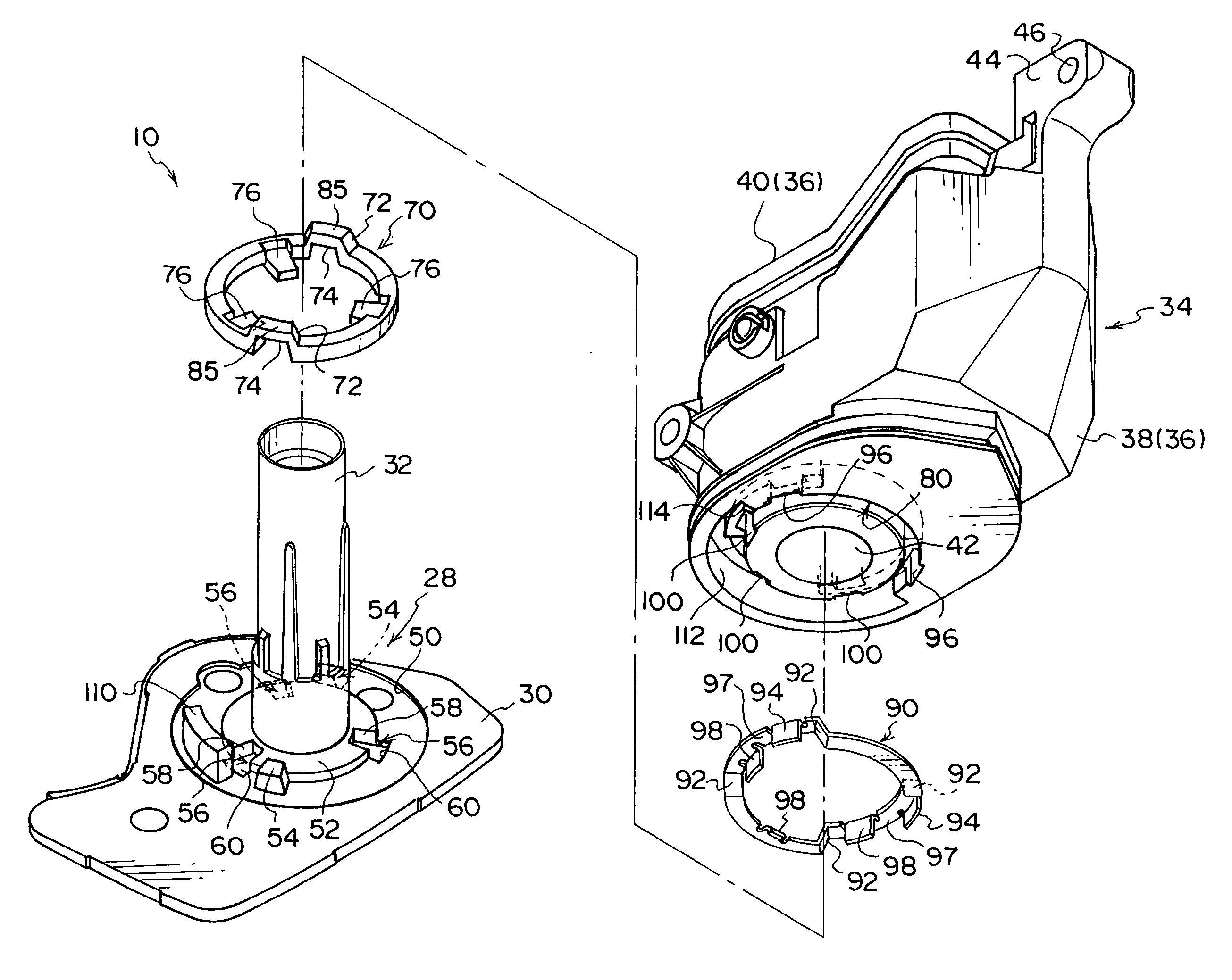
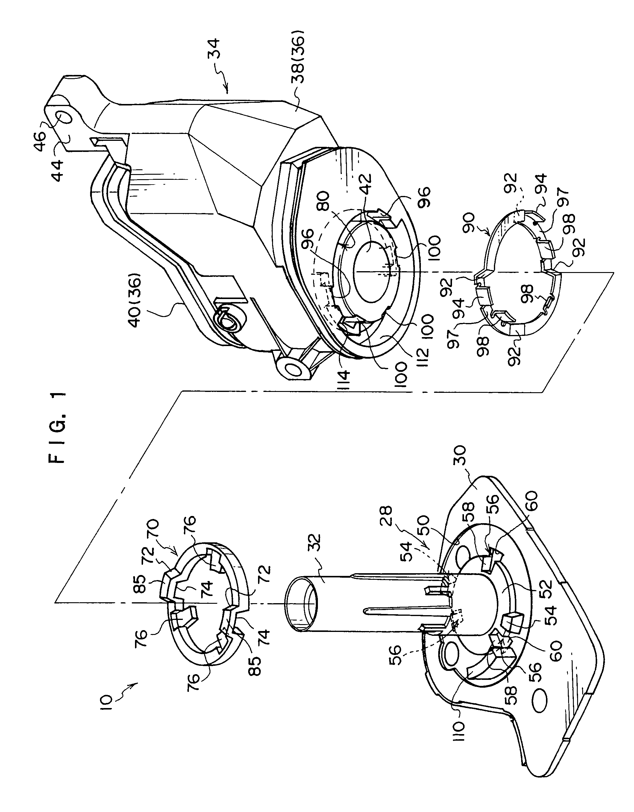
[0039]A front view of the overall structure of the vehicle door mirror device 10 of one embodiment of the present invention is shown in FIG. 4 where the device is in an exploded state.

[0040]As shown in FIG. 4, the vehicle door mirror device 10 is provided with a mirror device body 12, which is provided with a visor 14. The visor 14 is formed so as to be concave so the direction of the opening faces the approximate rear direction of the vehicle when, for example, the mirror device body 12 is in a state where it is turning toward an expanded position, which will be described later. A frame 16 is provided at the interior side of the visor 14.

[0041]The frame 16 is formed so as to be substantially board-shaped. A mirror surface angle-adjusting device (not shown) is attached to the frame 16. Further, a mirror 18 is arranged so as to be closer to the opening edge side of the visor 14 than the frame 16. The reflective surface of the mirror 18 is supported by the above-mentioned mirror surfa...


PUM


Abstract

A vehicle door mirror device has a detent plate which is provided in the bottom of a housing having a motor actuator therein and a detent piece which is arranged at a stand or a stay. Depressions are formed in the detent plate, protrusions are formed on the detent piece, and a stopper is provided on the stand. A restricting wall is provided at the bottom portion of the housing. The range of the turning angle of the housing is set from the state where the stopper is in contact with the restricting wall to where the protrusion on the detent piece comes into contact with the depression on the detent plate. The same detent piece can be used while changing the rotation angle of the housing by changing the position of the detent piece relative to the stand, whereby the types of parts used can be reduced.

Description

CROSS-REFERENCE TO RELATED APPLICATION[0001]This application claims priority under 35 U.S.C. 119 from Japanese Patent Application No. 2004-354149, the disclosure of which is incorporated by reference herein.BACKGROUND OF THE INVENTION[0002]1. Field of the Invention[0003]The present invention relates to rearview mirror device provided at a vehicle door panel. More specifically, the present invention relates to a door mirror device that can turn between an expanded position, where the mirrored surface faces towards the approximate rear direction of the vehicle, and a folded position, where the mirrored surface faces the interior of a cab in the vehicle's widthwise direction.[0004]2. Description of the Related Art[0005]An example of a means for a vehicle occupant to visually confirm what is behind the vehicle includes a door mirror provided on the door panel of the vehicle. An example of this type of door mirror is disclosed in the Gazette of the unexamined Japanese Utility Model No. 6...

Claims


Application Information

Patent Timeline
Patent Type & Authority Patents(United States)
IPC IPC(8): G02B7/18G02B7/182
CPCB60R1/074
Inventor YOSHIDA, SHIGEKI
Owner KK TOKAI RIKA DENKI SEISAKUSHO
Why Eureka
Try Eureka