
Power tube gate driving circuit and sectional driving method

A gate drive circuit and power tube technology, applied in the direction of output power conversion devices, electrical components, etc., can solve the problems of reducing EMI effect consistency, large capacitive load variation range, and large chip area, so as to reduce layout area and Cost, gate voltage rise time and fall time stability, effect of fewer device types

Active Publication Date: 2016-04-27
CRM ICBG (WUXI) CO LTD
View PDF6 Cites 23 Cited by
  • Summary
  • Abstract
  • Description
  • Claims
  • Application Information

AI Technical Summary

Problems solved by technology

[0009] In view of the above-mentioned shortcomings of the prior art, the purpose of the present invention is to provide a power tube gate drive circuit and a segmented drive method, which are used to solve the problem of using resistors, capacitors and other devices to achieve delay effects in the prior art, and the chip area occupied Large, and due to the large variation range of the capacitive load, the consistency of the EMI reduction effect is poor

Method used

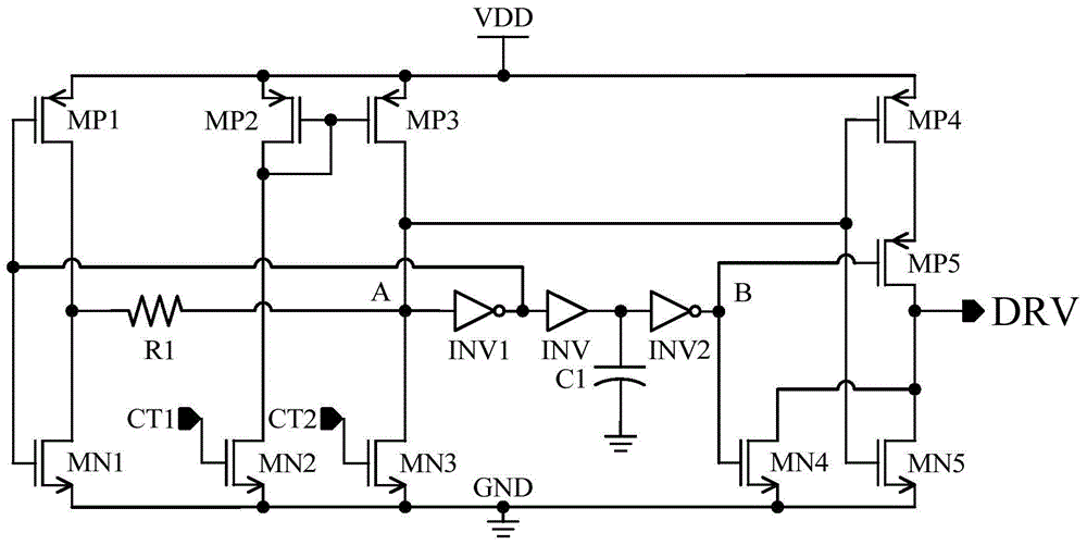
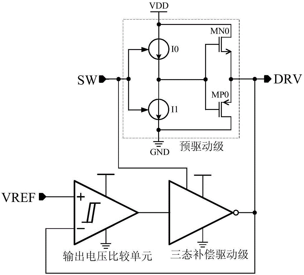
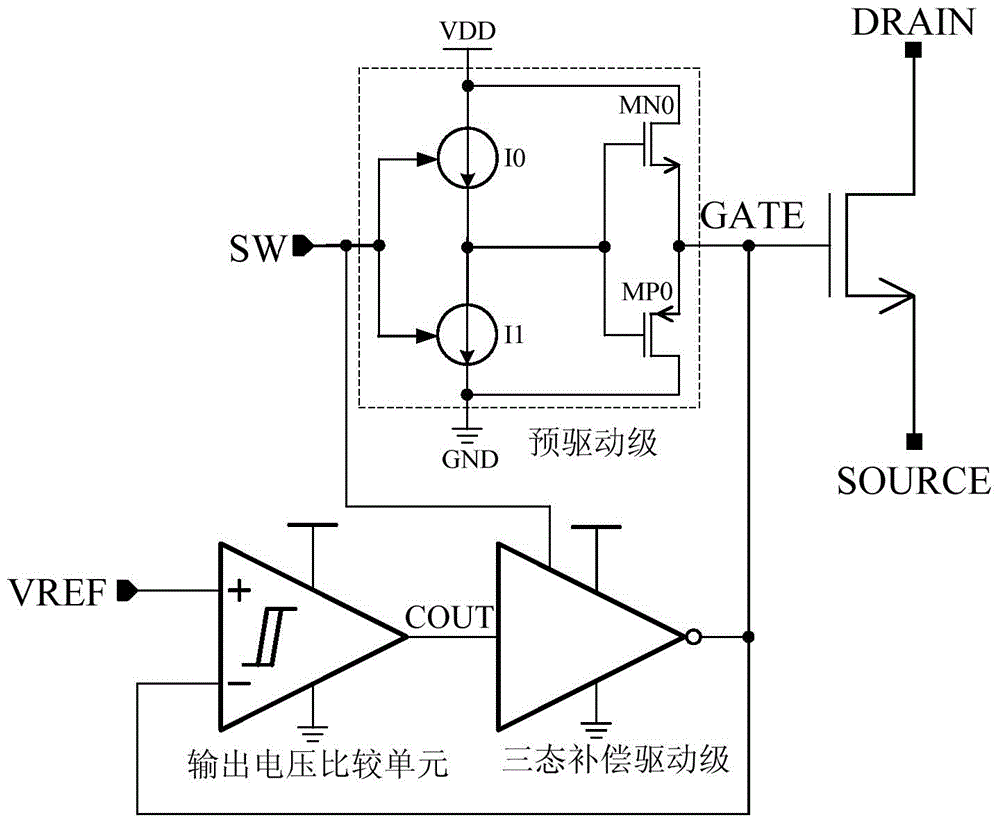

Image

  • Power tube gate driving circuit and sectional driving method
  • Power tube gate driving circuit and sectional driving method
  • Power tube gate driving circuit and sectional driving method

Examples


Embodiment Construction

[0053] Embodiments of the present invention are described below through specific examples, and those skilled in the art can easily understand other advantages and effects of the present invention from the content disclosed in this specification. The present invention can also be implemented or applied through other different specific implementation modes, and various modifications or changes can be made to the details in this specification based on different viewpoints and applications without departing from the spirit of the present invention.

[0054] see Figure 2 to Figure 6 . It should be noted that the diagrams provided in this embodiment are only schematically illustrating the basic idea of ​​the present invention, and only the components related to the present invention are shown in the diagrams rather than the number, shape and shape of the components in actual implementation. Dimensional drawing, the type, quantity and proportion of each component can be changed arb...


PUM


Abstract

The invention provides a power tube gate driving circuit and a sectional driving method. The power tube gate driving circuit comprises a pre-driving stage, an output voltage comparison unit and a tri-state compensation driving stage, wherein the pre-driving stage is used for controlling rising time and falling time of a driving signal, so as to switching on or off an insulated gate power switching device; the output voltage comparison unit is used for comparing voltage of the driving signal output by the pre-driving stage with a set threshold value, and then outputting a switching control signal; and the tri-state compensation driving stage is used for charging or discharging a driving output port in a compensatory manner under the enabling action of a switching control signal and the action of the switching control signal output by the output voltage comparison unit, and accelerating the driving output port to pull up or pull down, so as to fully switching on or off the insulated gate power switching device. The power tube gate driving circuit is simple in structure, requires no resistance and capacitance devices, reduces domain area, and has the advantages that gate charging / discharging speed is less affected by variation of capacitive loads, the efficiency is high, the driving circuit is safe and reliable, and the like. The sectional driving method can reduce EMI effectively and reliably.

Description

technical field [0001] The invention relates to the field of integrated circuits and control methods thereof, in particular to a power tube grid drive circuit and a segmented drive method. Background technique [0002] In the field of integrated circuit design, especially in the design of power management systems, gate drive loss has become a major factor that restricts the further improvement of system efficiency. EMI can be effectively reduced by controlling the switching mode of insulated gate power devices. Especially in the power management integrated circuit system, the insulated gate power device is often selected as the power switch, and the gate drive module unit of the insulated gate power switch device is indispensable. High-efficiency, low-cost, and low-EMI design are the keys to this type of gate driver cell design. In the existing gate drive circuit, a certain switch dead time is often set to achieve high efficiency, improve the gate charge and discharge effec...

Claims


Application Information

Patent Timeline
Patent Type & Authority Applications(China)
IPC IPC(8): H02M1/088
Inventor 吴传奎闾建晶苏崇高田荣华
Owner CRM ICBG (WUXI) CO LTD
Learn More