
Sheet coil type resolver

a resolver and coil technology, applied in the field of sheet coil resolvers, can solve the problems of easy distortion of shape, difficult downsizing, and easy stress concentration of the area between the rotary shaft and the rotor core, and achieve the effect of reducing the length of lead wires, reducing the radial dimension, and less problems

Active Publication Date: 2011-02-24
MINEBEAMITSUMI INC
View PDF2 Cites 24 Cited by
  • Summary
  • Abstract
  • Description
  • Claims
  • Application Information

AI Technical Summary

Benefits of technology

[0013]The present invention has bee made in light of the problems described above, and it is an object of the present invention to provide a sheet coil type resolver in which the diameter can be reduced and at the same time wirings from sheet coils can be easily done, and which has a high reliability.
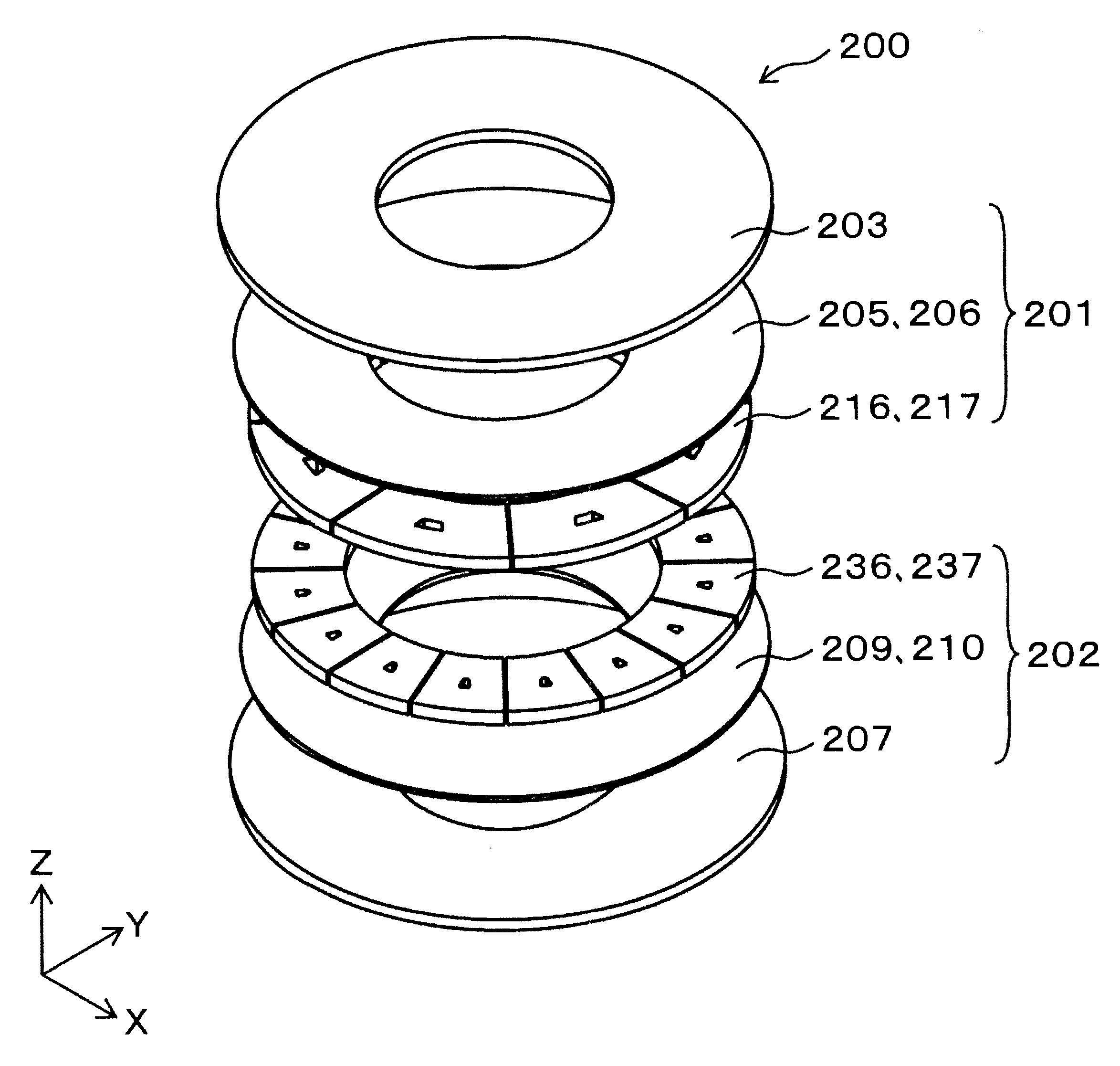
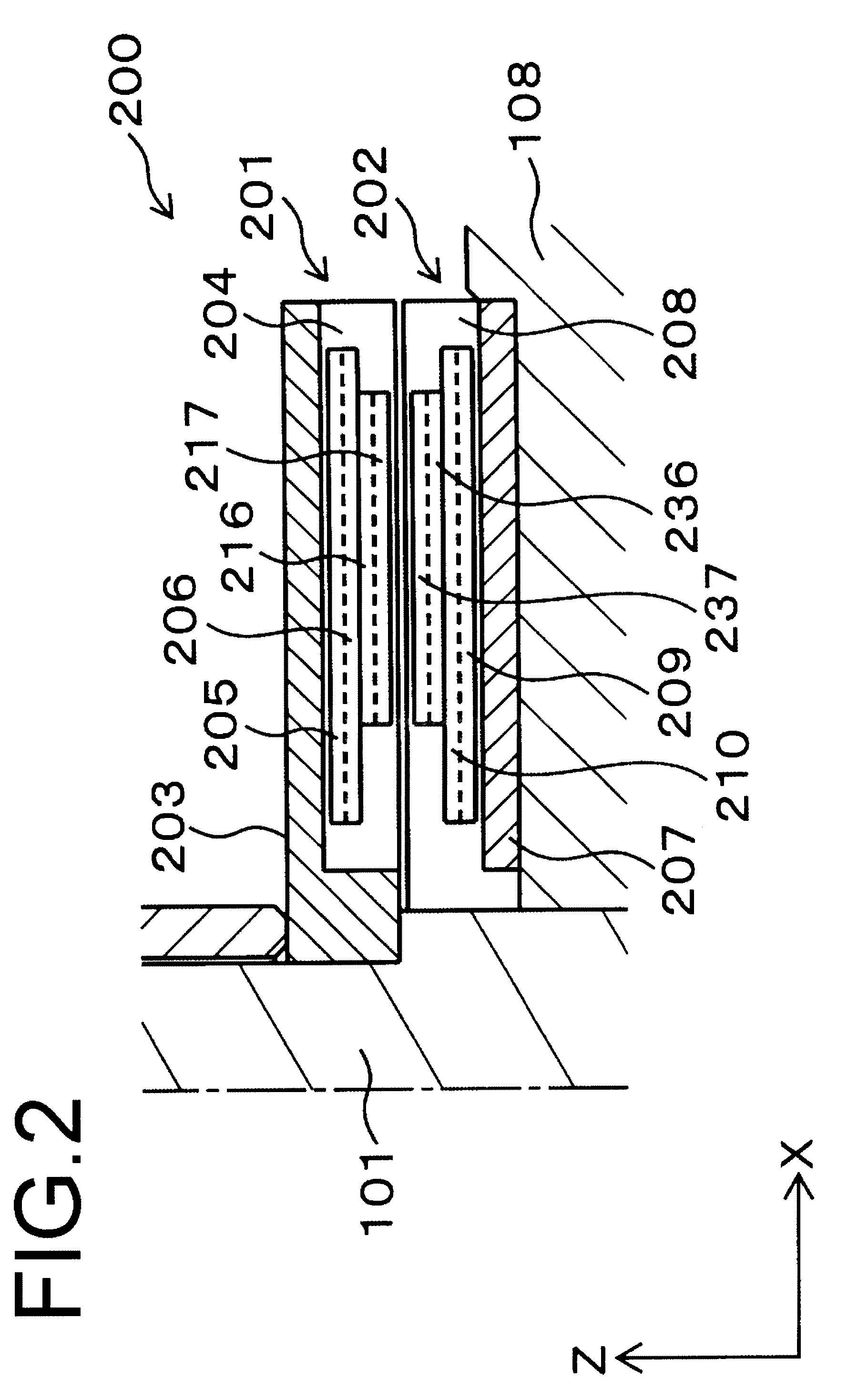
[0021]According to the present invention, since respective coils are disposed on different planes so as to axially overlap with each other in a sheet coil, the radial dimension can be reduced, and thus the sheet coil type resolver can be downsized. Also, since no other sheet coil is provided around one sheet coil, lead wires can be easily led out from the sheet coil. Further, since the length of such lead wires is reduced, the wires suffer less problems, such as wire breakage, and high reliability can be achieved.

Problems solved by technology

Thus, in the above described coil arrangement at each of the rotor section and the stator section, two kinds of coils are disposed concentrically to each other on one plane with one coil located radially outward of the other coil located close to the rotary shaft, and therefore both the rotor section and the stator section are forced to have an enlarged diameter thus making downsizing difficult.
Also, the rotor core and the stator core are inevitably forced to have an enlarged diameter, too, and therefore apt to suffer distortion in shape.
Further, since the distance is large between the rotary shaft and the outer circumference of the resolver, the centrifugal force is easily generated and accordingly the area between the rotary shaft and the rotor core is susceptible to stress concentration.
Consequently, it is possible that the rotor section and the rotary shaft are shifted from each other and also that the joint area therebetween is fractured.

Method used


Image

  • Sheet coil type resolver
  • Sheet coil type resolver
  • Sheet coil type resolver

Examples


Embodiment Construction

[0036]Exemplary embodiments of the present invention will hereinafter be described with reference to the companying drawings.

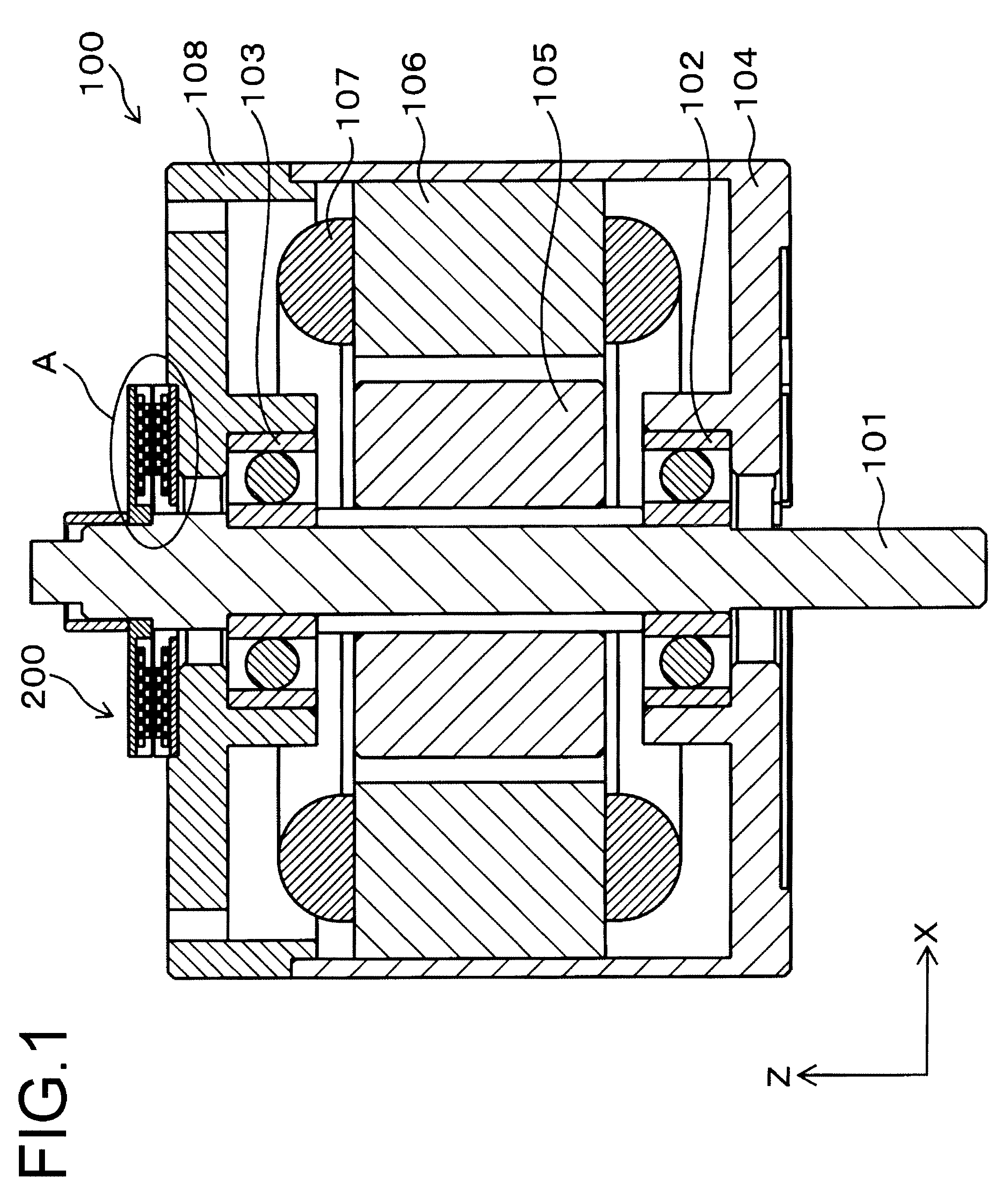
[0037]First, description will be made of a motor to which a sheet coil type resolver of the present invention is attached. FIG. 1 shows an axial cross section of a motor 100 to which any one of sheet coil type resolvers according to the present invention is attached. Referring to FIG. 1, the motor 100 is an AC servo motor and includes a rotary shaft 101. The rotary shaft 101 is rotatably supported by bearings 102 and 103. The bearing 102 is attached to a motor housing 104 and the bearing 103 is attached to a rear end cap 108 fixed to the rear end (upper side in the figure) of the motor housing 104. Thus, the rotary shaft 101 is supported rotatably with respect to the motor housing 104. A motor rotor 105 constituted by a permanent magnet having a plurality of magnetic poles is attached to the rotary shaft 101.

[0038]A motor stator core 106 is disposed to radiall...


PUM


Abstract

A sheet coil type resolver includes: a stator section in which a stator transformer coil composed of first and second stator transformer coil layers is disposed to axially overlap with a resolver stator coil composed of first and second resolver stator coil layers; and a rotor section in which a rotor transformer coil composed of first and second rotor transformer coil layers is disposed to axially overlap with a resolver rotor coil composed of first and second resolver rotor coil layers, whereby the axial dimension is reduced, lead wires can be easily led out from the coils, and high reliability is achieved.

Description

CROSS REFERENCE TO RELATED APPLICATIONS[0001]This application is based upon and claims the benefit of priority from prior Japanese Patent Application No. 2009-190928, filed on Aug. 20, 2009;[0002]the entire contents of which are incorporated herein by reference.BACKGROUND OF THE INVENTION[0003]1. Field of the Invention[0004]The present invention relates to a sheet coil type resolver which uses a sheet coil as its electric conductor.[0005]2. Description of the Related Art[0006]A conventional sheet coil type resolver is disclosed and includes: an excitation coil of a single phase which is formed of a flat sheet coil such that the angle of each pole of pole-pair number X is 180 degrees in electrical angle; and a detection coil of two phases (phases A and B) which is formed of a flat sheet coil and disposed to axially oppose the excitation coil with a gap distance therebetween wherein phases A and B have a phase difference of 90 degrees in electrical angle from each other (refer to Japa...

Claims


Application Information

Patent Timeline
IPC IPC(8): G01B7/30
CPCG01D5/2046
Inventor FUJITA, KAZUHIKOFUKUDA, TAKAKOOCHIAI, TAKAAKI
Owner MINEBEAMITSUMI INC
Learn More