Beveled tonsil suction cautery dissector

a tonsil and cautery technology, applied in the field of surgical devices, can solve the problems of chronic infection, unresponsive to medical therapy, and inability to physically remove the tonsil reservoir of infection, and achieve the effect of minimal thermal trauma and rapid tissue cutting

Active Publication Date: 2007-01-30
OHALLORAN LAURENCE R
View PDF18 Cites 18 Cited by
  • Summary
  • Abstract
  • Description
  • Claims
  • Application Information

AI Technical Summary

Benefits of technology

[0028]Suction at the tip of the cautery device allows rapid clearing of blood from the field and direct cautery application to the site of bleeding. Currently available suction tips are rounded and blunt making them inappropriate for rapid cutting of tissue. Introducing a bevel and angle to the suction tip corrects this problem. In one embodiment, no insulation is provided around the distal circumference of the tip which allows tissue contact with the full extent of the suction tube. The angle of the tip positions the suction hole directly parallel to the plane of the bleeding site. In particular, the angle is superbly oriented for cauterization of the superior...

Problems solved by technology

They are large in the younger years but progressively atrophy as the patient ages.
Chronic tonsillitis occurs when bacteria is retained in or trapped by tonsillar tissue and this leads to chronic infection which eventually becomes unresponsive to medical therapy using antibiotics.
When the frequency of infection becomes excessive, physical removal of the tonsillar reservoir of infection becomes necessary.
Tonsillar hypertrophy or the development of excessively large tonsils leads to obstructive breathing problems and airway obstruction and is associated with sleep apnea.
Indeed, there are many problems with the PDD.
First, with respect to tip shape and angulation, the PDD...

Method used


Image

  • Beveled tonsil suction cautery dissector
  • Beveled tonsil suction cautery dissector
  • Beveled tonsil suction cautery dissector

Examples


Embodiment Construction

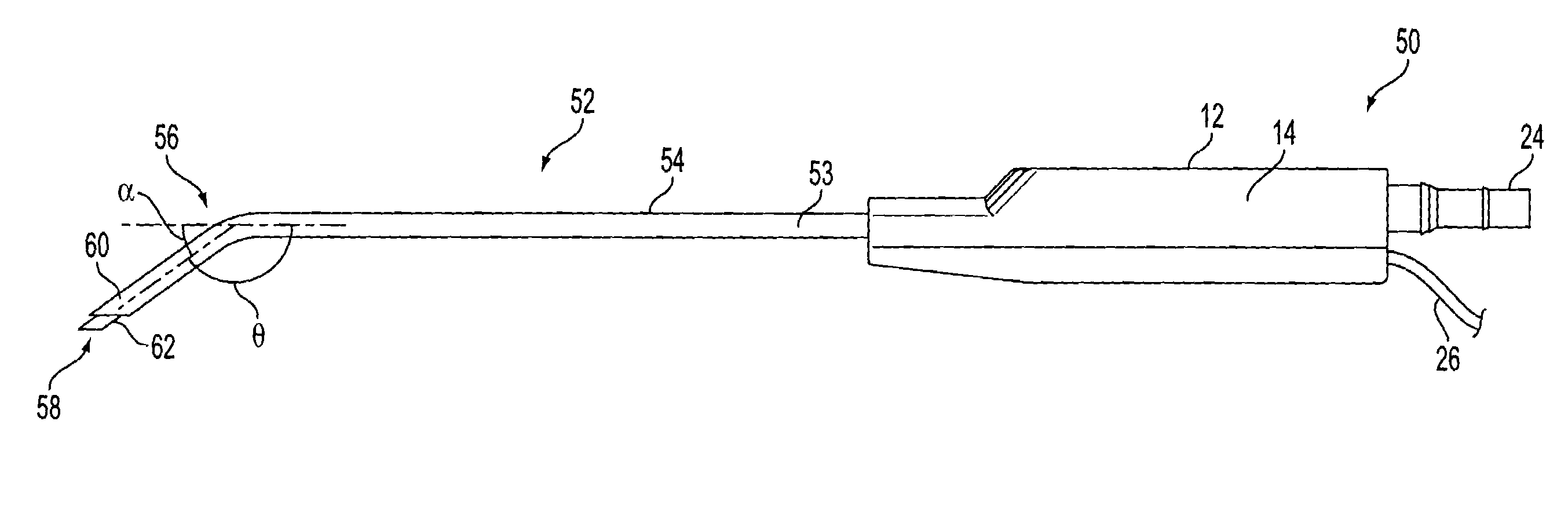
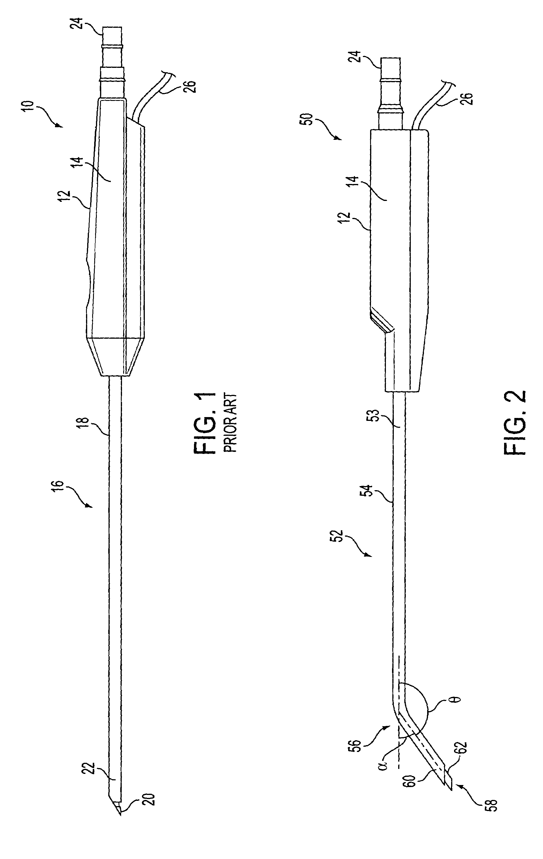
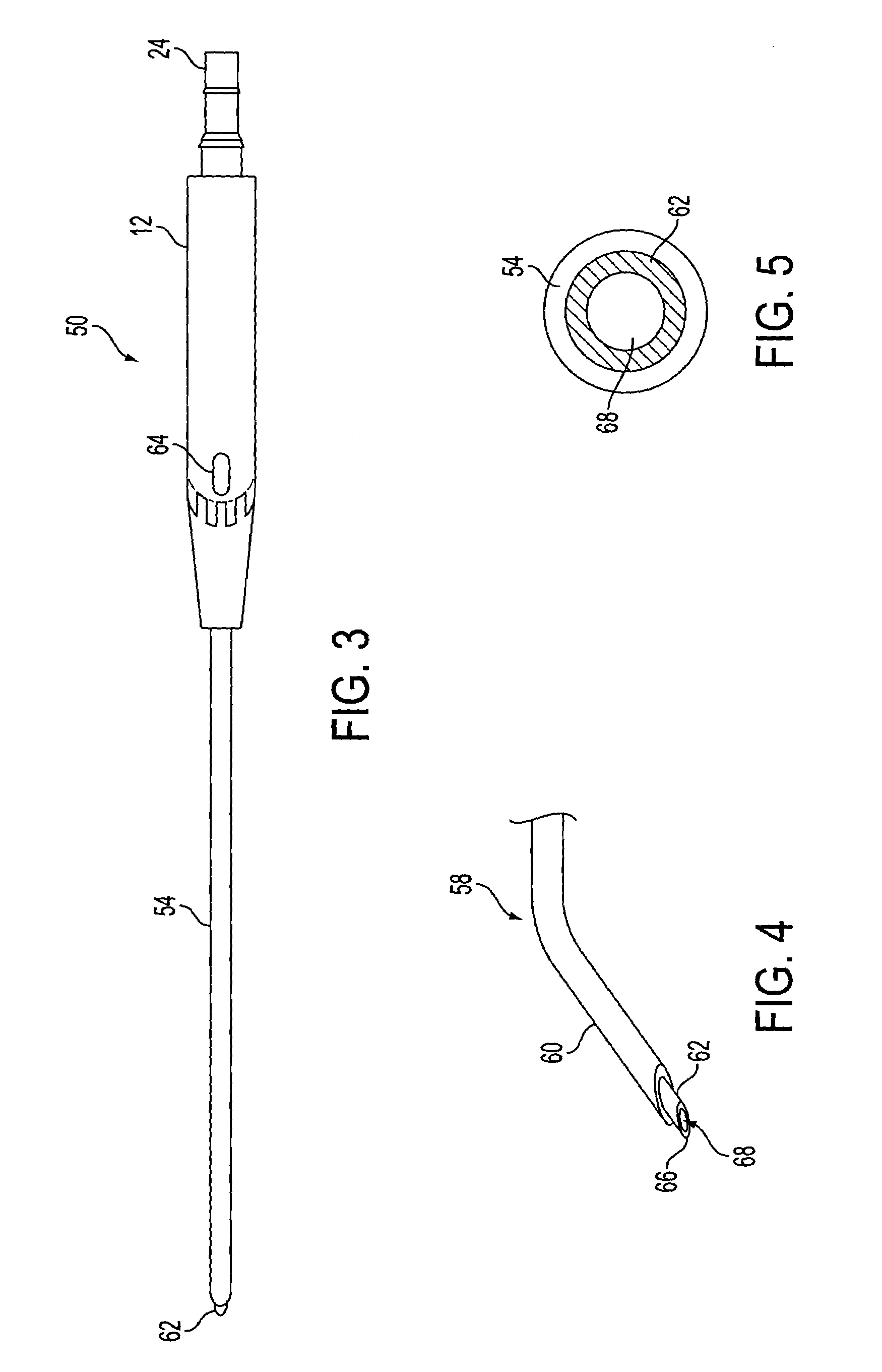
[0050]As discussed above, various embodiments and iterations of the present invention relate to an improved suction cautery dissector as depicted, for example, in FIGS. 2, 3–5, 7, 9, 10, 12, 14, and 16. FIG. 2 depicts a suction cautery dissector 50 that provides a handle assembly 12 and an optional handle gripping mechanism 14. As depicted in FIG. 2, a groove or ridge may be provided for handle gripping mechanism 14. Also, any other similar structure may be used to enable the surgeon or other user to get a better grip on the handle of the device. This structure is optional or may be enhanced with additional such structures around the periphery of handle assembly 12. In addition, the shape and size of the handle assembly 12 may be modified to provide better gripping for the surgeon using the tool as will be appreciated by those of ordinary skill in the art.

[0051]Connected into handle assembly 12 may be provided an insulated metal tubing assembly 52. According to one embodiment, a met...


PUM


Abstract

A suction cautery dissector comprising a handle assembly, a tubing assembly having a suction channel formed therein, the tubing assembly comprising a first portion connected to the handle assembly and a distal end, and a tip assembly at the distal end of the insulated tubing assembly, the tip assembly comprising a substantially co-planar, enclosed cautery surface with a beveled leading edge sharpened for dissecting tissue. The cautery surface provides an opening formed therein that communicates with the suction channel in the insulated tubing assembly and being operably connected to an electrical source. The tip assembly comprises a tip wall terminating at the cautery surface and wherein the tubing assembly comprises an insulating layer covering the suction channel from the first portion to the distal end, terminating at a minimum predetermined distance along the tip wall from the cautery surface around the circumference of the tip assembly to enable the tip assembly to make surface contact around the entire tip wall.

Description

RELATED APPLICATIONS[0001]This application claims priority from U.S. Provisional Patent Application No. 60 / 409,199 filed on Sep. 10, 2002 entitled “Beveled tonsil suction cautery dissector.”FIELD OF THE INVENTION[0002]The present invention relates to the field of surgical devices used for dissection of tissue in confined spaces.BACKGROUND OF THE INVENTION[0003]About Tonsillectomy[0004]Tonsillectomy is one of the most commonly performed surgical procedures in the United States with approximately 400,000 operations conducted per year. The tonsils are masses of lymphoid tissue that are embedded in the lateral wall of the pharynx or throat. They are large in the younger years but progressively atrophy as the patient ages. Tonsillectomy is the surgical procedure performed typically under general anesthesia in which the tonsils are removed from the patient's throat in order to treat a disease state involving the tonsils.[0005]Indications for Tonsillectomy[0006]The two disease processes th...

Claims


Application Information

Patent Timeline
IPC IPC(8): A61B18/18A61B18/14
CPCA61B18/1485A61B17/32A61B2218/007A61B2018/00595
Inventor O'HALLORAN, LAURENCE R.
Owner OHALLORAN LAURENCE R
Why Eureka
Try Eureka