Anastomosis instrument and method for performing same

an anastomosis and tubular body technology, applied in the field of anastomosis instruments and methods, can solve the problems of requiring a large recovery period, and patients with significant attendant risks, and achieve the effect of reducing the possibility of slippag

Inactive Publication Date: 2007-01-30
TYCO HEALTHCARE GRP LP
View PDF150 Cites 211 Cited by
  • Summary
  • Abstract
  • Description
  • Claims
  • Application Information

AI Technical Summary

Benefits of technology

[0018]In one embodiment, the arcuate portions extend beyond the diameter of the loops of the retaining ring and are deformable to a substantially straightened configuration upon deformation of the surgical fasteners. The surgical fasteners are preferably mounted within the DLU (or SULU) in an offset manner such that upon retraction of the anvil, the distal end of the fasteners deform at an angle a relative to the proximal end thereof which, in turn, forcibly expands the tissue ring outwardly and deforms the arcuate portions to a substantially straightened configuration. As a result, the tissue ring is held in slight tensile engagement atop the array of surgical fasteners which reduces the possibility of slippage after deformation of the surgical fasteners.

Problems solved by technology

However, such procedures that involve large incisions and substantial displacement of the rib cage are often traumatic to the patient with significant attendant risks.
The recovery period may be extensive and is often painful.
Furthermore, patients for whom coronary surgery is indicated may need to forego such surgery due to the risks involved with gaining access to the heart.
Such procedures require the introduction of multiple catheters into the blood vessels adjacent the heart, which is a complicated procedure requiring that the desired vessels be properly located and accessed.
Furthermore, the introduction of catheters form punctures in the blood vessels that must be subsequently closed, and there is an increased risk of trauma to the interior walls of the vessels in which the catheters must pass.
However, conventional suturing is complicated by the use of minimally invasive procedures, such as the window approach, e.g., limited access and reduced visibility to the surgical site may impede the surgeon's ability to manually apply sutures to a graft.
Additionally, it is difficult and time consuming to manually suture if the CABG procedure is being performed while the heart is beating as the suturing must be synchronized with the heart beat.
As can be appreciated, the process of manually suturing the harvested vessel segment to a coronary artery is time consuming and requires a great deal of skill on the part of the surgeon.
In minimally invasive procedures such as in MIDCAB, the ability to suture is even more complicated due to limited maneuverability and reduced visibility.

Method used


Image

  • Anastomosis instrument and method for performing same
  • Anastomosis instrument and method for performing same
  • Anastomosis instrument and method for performing same

Examples


Embodiment Construction

[0077]Preferred embodiments of the surgical instrument and method disclosed herein will be described in terms of a coronary artery bypass procedure wherein a vascular anastomosis is created by joining a section of a harvested vessel, e.g., the saphenous vein, to bypass an occlusion in a coronary artery, e.g., the left anterior descending artery (“LAD”). Alternatively, the presently disclosed surgical instrument may also be utilized in performing anastomosis of other tubular luminal body structures.

[0078]In the drawings and in the description which follows, the term “proximal”, as is traditional, will refer to the end of the apparatus which is closer to the user, while the term “distal” will refer to the end which is further from the user.

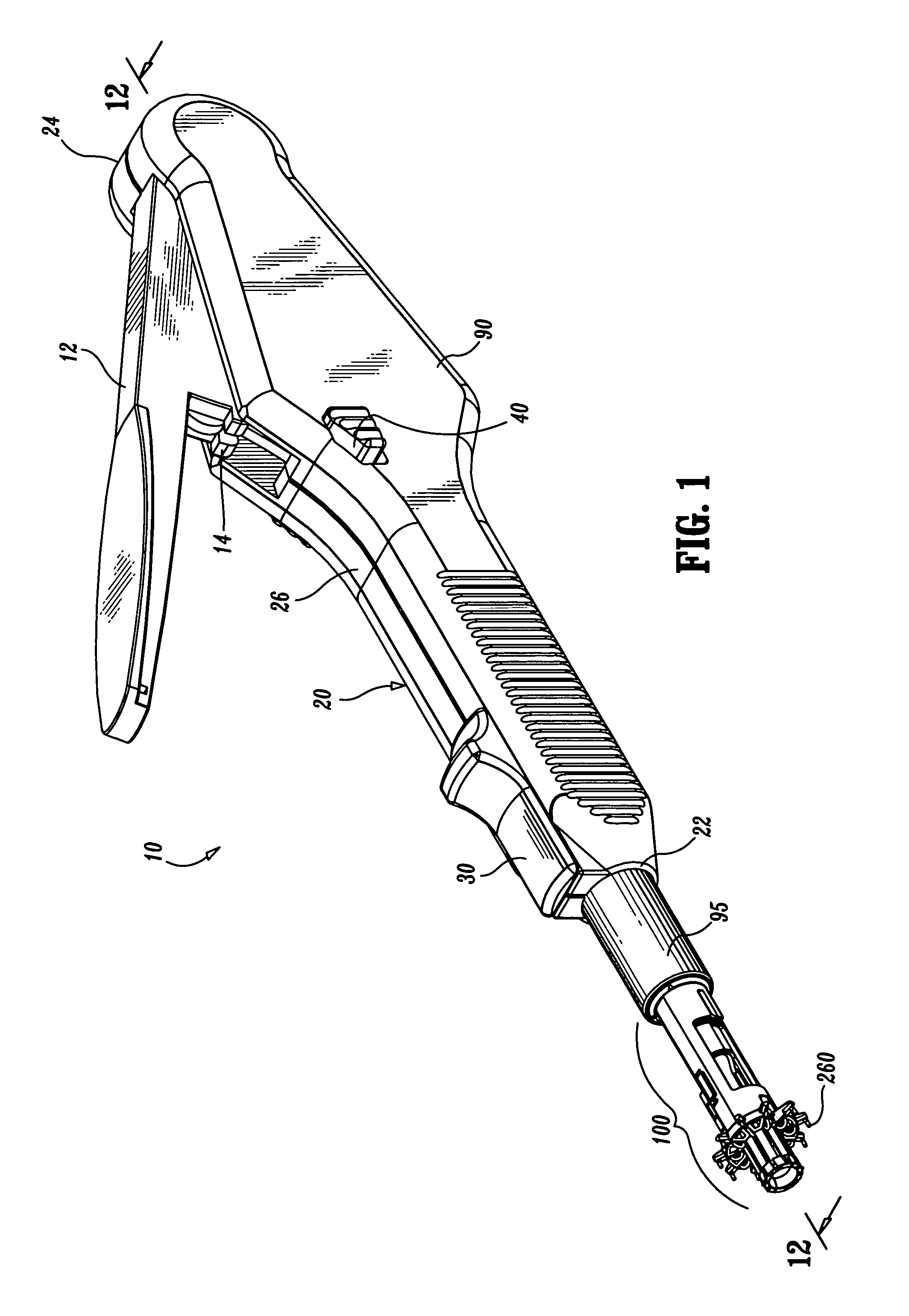
[0079]Referring now in detail to the drawing figures in which like reference numerals identify similar or identical elements, one embodiment of the present disclosure is illustrated generally in FIG. 1 and is designated therein as surgical instrumen...


PUM


Abstract

A tissue retaining ring for use with a plurality of surgical fasteners mounted within a disposable loading unit utilized during a vascular anastomosis inlcudes a genrally circular, semi-pliable material having a series of alternating loops and arcuate portions. Each of the loops defines an aperture therein which is dimensioned to receive a distal end of one of the plurality of surgical fasteners. When the instrument is fired, the surgical fasteners are simultaneously deformed through the tissue ring and through the tissue. The tissue retaining ring holds the tissue in place along the surgical fastener and reduces the chances of tissue slippage after deformation.

Description

CROSS REFERENCE TO RELATED APPLICATIONS[0001]This application claims priority to U.S. Application Ser. No. 60 / 241,301 entitled “ANASTOMOSIS INSTRUMENT AND METHOD FOR PERFORMING SAME” filed on Oct. 18, 2000 by Keith Milliman et al. which is a continuation-in-part application of U.S. application Ser. No. 09 / 410,817, entitled “ANASTOMOSIS INSTRUMENT AND METHOD FOR PERFORMING SAME” which was filed on Oct. 9, 1999 by Keith Milliman et al., which is a continuation-in-part of U.S. application Ser. No. 09 / 256,260, entitled “ANASTOMOSIS INSTRUMENT AND METHOD” which was filed on Feb. 23, 1999 by Nicholas et al., which is a continuation-in-part of U.S. application Ser. No. 08 / 877,701, entitled “SINGLESHOT ANASTOMOSIS INSTRUMENT WITH DETACHABLE LOADING UNIT AND METHOD”, which was filed Jun. 17, 1997 by Manzo et al., which application is a continuation-in-part of U.S. application Ser. No. 08 / 685,385, entitled “ANASTOMOSIS INSTRUMENT AND METHOD”, filed Jul. 23, 1996 by Hinchliffe et al., now U.S....

Claims


Application Information

Patent Timeline
Patent Type & Authority Patents(United States)
IPC IPC(8): A61B17/04A61B17/064A61B17/11A61B17/115A61B17/28A61B17/32
CPCA61B17/11A61B17/0644A61B17/115A61B2017/2916A61B2017/0641A61B2017/1107A61B2017/1135A61B17/32053
Inventor SNIFFIN, KEVINMANZO, SCOTT E.ORBAN, JOSEPH P.HEATON, LISA W.HINCHLIFFE, PETER W. J.MILLIMAN, KEITH L.NICHOLAS, DAVID A.
Owner TYCO HEALTHCARE GRP LP
Why Eureka
Try Eureka