
Solid expandable tubular members formed from very low carbon steel and method

Active Publication Date: 2007-01-30
U S STEEL TUBULAR PROD
View PDF143 Cites 17 Cited by
  • Summary
  • Abstract
  • Description
  • Claims
  • Application Information

AI Technical Summary

Benefits of technology

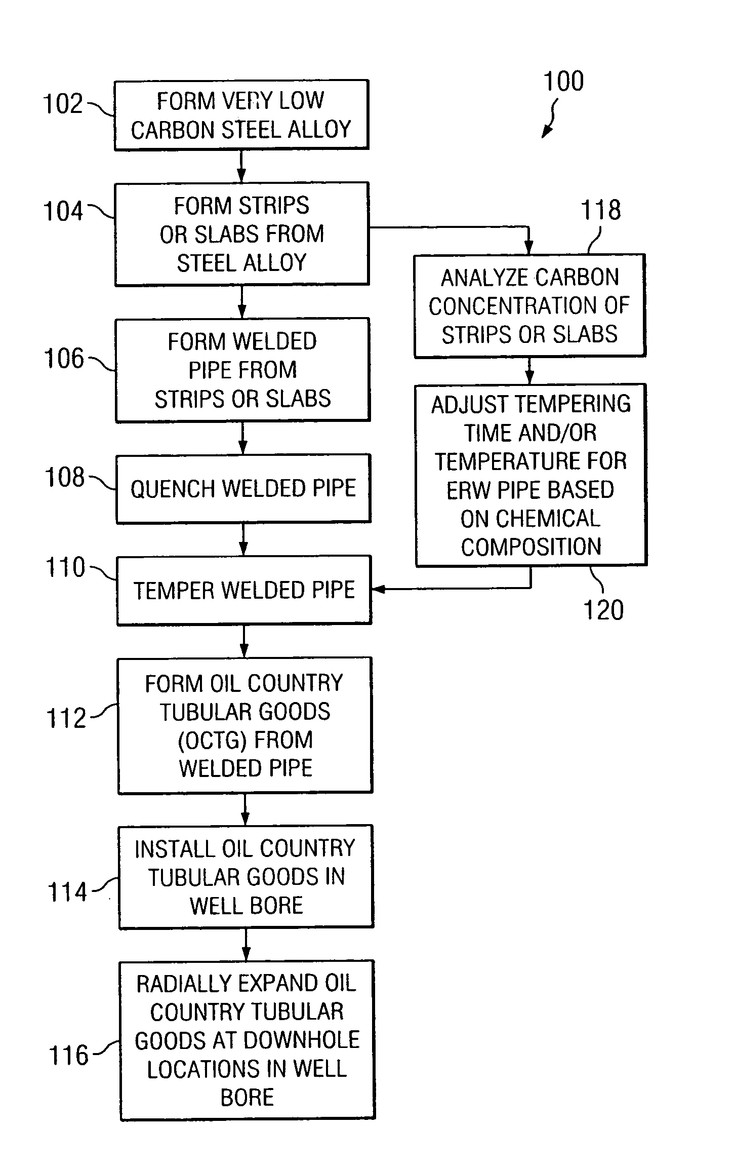
[0009]Technical benefits of the present invention include providing steel alloys with very low carbon concentrations satisfactory for use in forming solid, expandable tubular members which may be radially expanded from approximately twenty percent (20%) to forty-five percent (45%) or greater. After such radial expansion, the tubular members may still provide required mechanical strength and fluid tight integrity for satisfactory completion of a wellbore and production of formation fluids.
[0010]Further technical benefits of the present invention include providing solid, expandable tubular member formed from very low carbon steel alloys that substantially reduce or eliminate requirements for telescoping or tapering of wellbores from an associated well surface to a desired downhole location. Such tubular members preferably maintain both desired mechanical strength and fluid tight integrity during radial expansion within a wellbore. Expandable tubular members formed in accordance with teachings of the present invention may allow wells to be completed to relatively deep geological locations or at extended distances from a production platform which may have been difficult and / or expensive to reach using traditional well drilling and casing technology. The use of such solid, expandable tubular members may allow wellbores to be drilled and completed with only one or two sizes of casing extending from a well surface to a relatively deep downhole location and / or extended reach location. As a result of requiring only one or two sizes of casing to complete a wellbore, surface equipment, associated drilling rigs, drill strings, drill bit sizes and downhole well completion equipment may be standardized to significantly reduce costs.
[0011]For some applications tubular members formed in accordance with teachings of the present invention may be radially expanded by as much as twenty percent (20%) to forty five percent (45%) of their original inside diameter and satisfactorily hold as much as three thousand five hundred pounds per square inch (3,500 psi) of internal fluid pressure after such radial expansion. Tubular members formed from only low carbon steel alloys in accordance with teachings of the present invention provide required mechanical strength to complete deep and / or extended reach wellbores and provide required fluid pressure tight seals between the interior and the exterior of associated tubular members.
[0012]Quench and temper procedures are often limited to use with high carbon steel alloys and medium carbon steel alloys. Quenching and tempering very low carbon steel alloys is a relatively unusual procedure. Normalizing is a more common technique associated with very low carbon steel alloys. Quenching and tempering very low carbon steel alloys formed in accordance with teachings of the present invention may result in relatively high ductility appropriate for radial expansion of resulting tubular members in the range of approximately twenty percent to forty-five percent. Quenching and tempering very low carbon steel alloys formed in accordance with teachings of the present invention typically produces relatively fine grain structures and relatively high yield strengths associated with oil country tubular goods. Quenching and tempering very low carbon steel alloys formed in accordance with teachings of the present invention results in higher yield strength as compared with normalizing the same very low carbon steel alloys. Fracture toughness of the resulting tubular members may also be increased.

Problems solved by technology

Each change in casing diameter often results in decreasing the diameter of production tubing used to produce formation fluids from a desired downhole location.
Changes in casing diameter associated with deep wells and / or long wells result in significantly increased drilling and completion costs for associated wells.
Martensite is sometimes difficult to obtain during quenching of low carbon steel alloys and very low carbon steel alloys.

Method used


Image

  • Solid expandable tubular members formed from very low carbon steel and method
  • Solid expandable tubular members formed from very low carbon steel and method
  • Solid expandable tubular members formed from very low carbon steel and method

Examples


Embodiment Construction

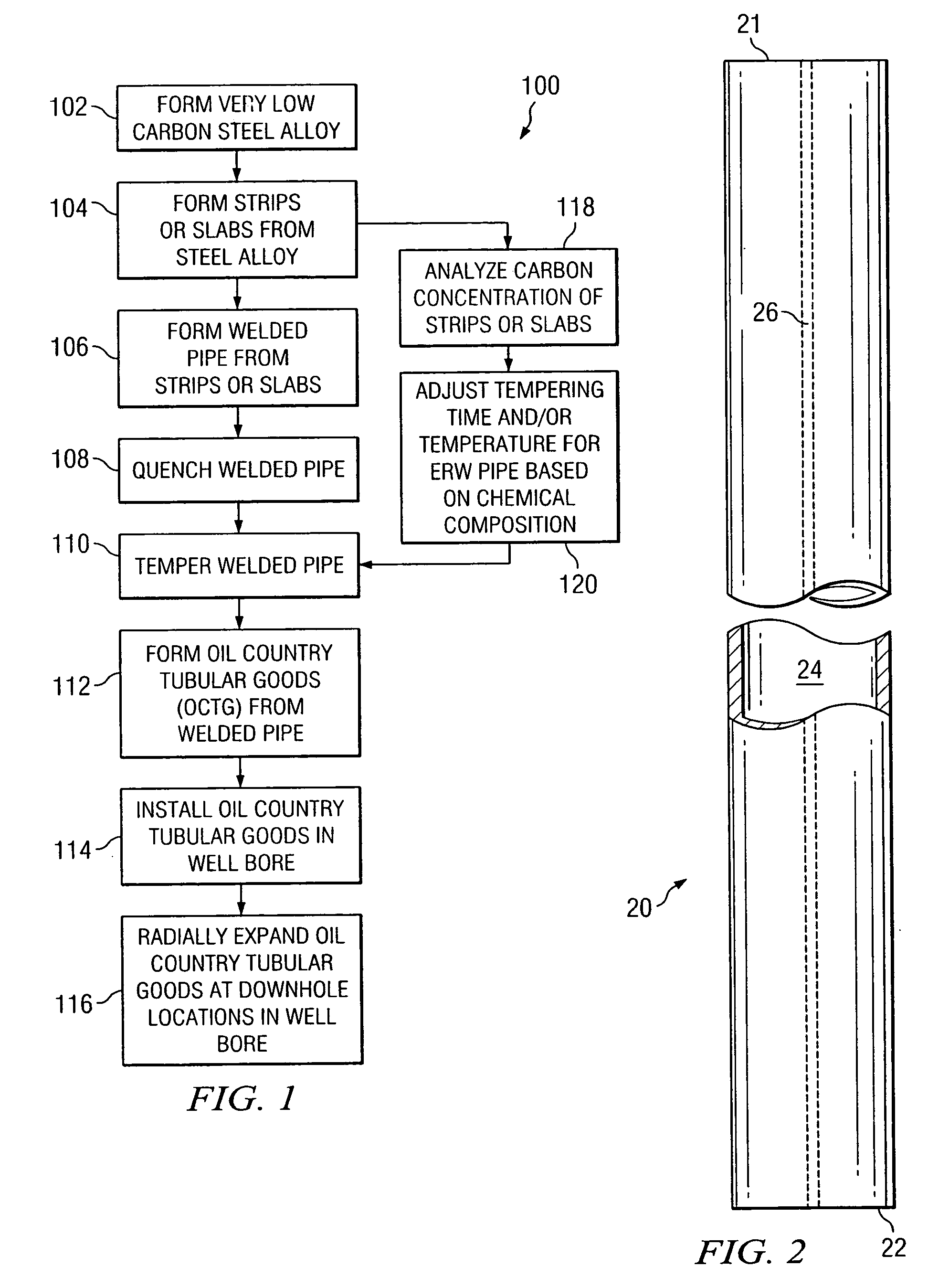
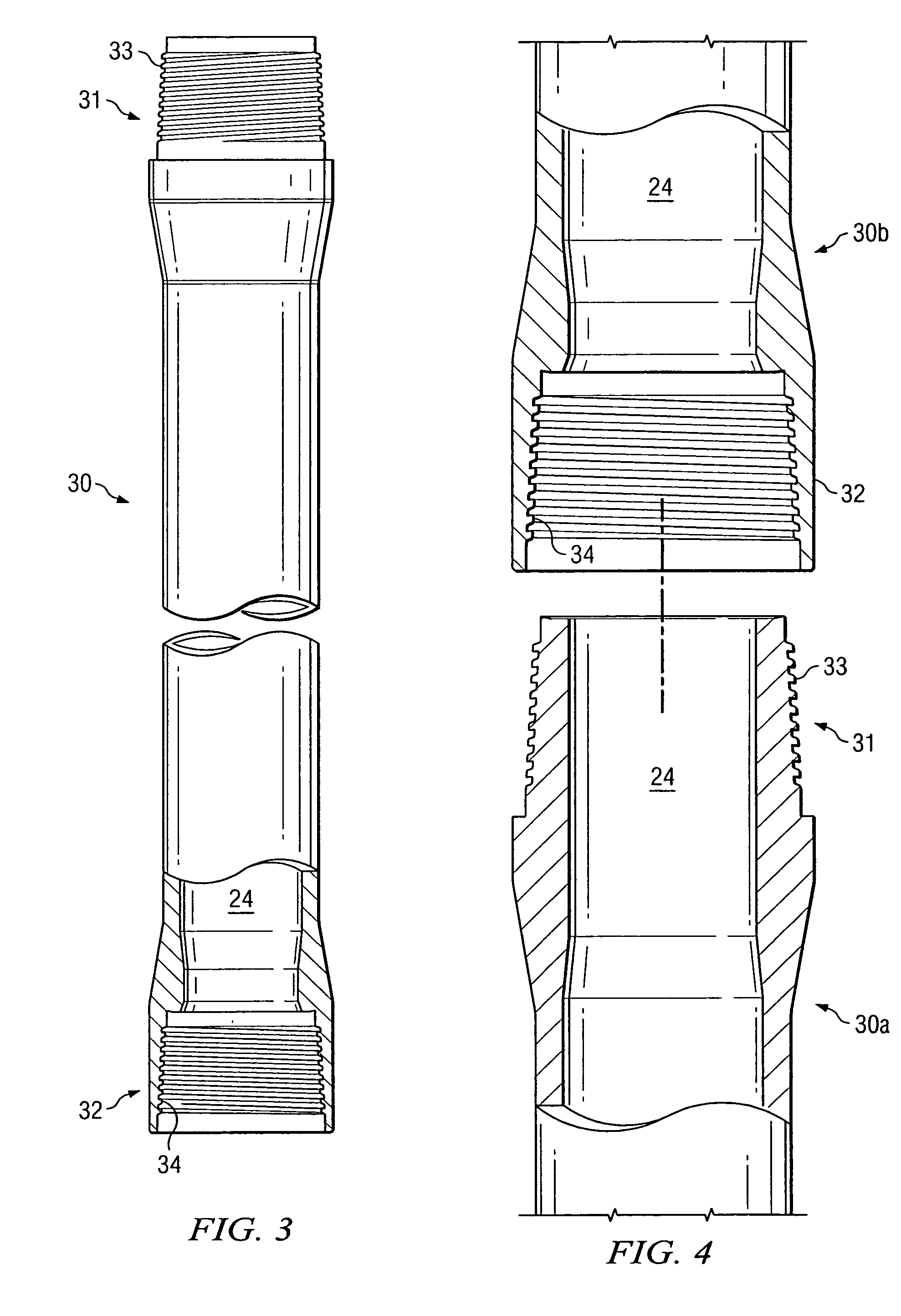
[0020]Preferred embodiments of the invention and its advantages are best understood by reference to FIGS. 1–6 wherein like numbers refer to same and like parts.

[0021]The term “very low carbon steel alloys” may be used in the steel industry to describe steel alloys with a concentration of carbon between approximately 0.001% and 0.1% by weight of the steel alloy. Low carbon steel alloys or mild steel often contains between approximately 0.1% and 0.3% carbon. Medium carbon steel alloys may contain between approximately 0.3% and 0.7% carbon. High carbon steel alloys may contain between approximately 0.7% and 1.5% carbon.

[0022]Very low carbon steel alloys formed in accordance with teachings of the present invention preferably have carbon concentrations of between approximately 0.03% and 0.06% by weight of the steel alloy. Such very low carbon steel alloys may also have at least ninety percent (90%) iron by weight of the steel alloy and at least ninety (90%) martensite by volume of the st...


PUM

PropertyMeasurementUnit
Temperatureaaaaaaaaaa

Abstract

A very low carbon steel alloy is provided for use in manufacturing tubular members such as oil country tubular goods. The tubular members may be radially expanded from at least twenty percent to forty percent. Sections or joints of casing formed from the steel alloy may be installed within a wellbore and radially expanded during completion of the wellbore.

Description

TECHNICAL FIELD[0001]The present invention is related in general to materials and methods used to form expandable tubular members and in particular steel alloys and methods for producing oil country tubular goods which may be radially expanded within a wellbore.BACKGROUND OF THE INVENTION[0002]Wellbores for producing oil, gas or other fluids from subsurface formations are often drilled in stages. For example, a wellbore may first be drilled with a drill string and a first drill bit having a relatively large diameter. At a desired depth for a first portion of the wellbore, the drill string and drill bit are removed from the wellbore. A tubular member of smaller diameter, often referred to as a casing or a casing string, may then be placed in the first portion of the wellbore. An annulus formed between the inside diameter of the wellbore and the outside diameter of the casing string is generally filled with cement. The cement provides support for the casing and isolates downhole forma...

Claims


Application Information

Patent Timeline
IPC IPC(8): C22C38/00E21B43/10F16L9/02F16L15/00
CPCE21B43/103E21B43/106F16L15/001F16L9/02Y10T403/5746
Inventor REAVIS, GARY M.LOWERY, BLUFORD W.MYERS, RALPH R.URECH, BOWMAN A.
Owner U S STEEL TUBULAR PROD
Learn More