Pyrolysis tube and pyrolysis method for using the same

a technology of pyrolysis tube and pyrolysis method, which is applied in the direction of liquid degasification, lighting and heating apparatus, separation processes, etc., can solve the problems of reducing the heat transfer rate, shortening the longevity of the pyrolysis tube, and more intensive secondary reactions of the olefins, so as to achieve not adversely increase the pressure drop

Inactive Publication Date: 2007-01-30
LG CHEM LTD
View PDF13 Cites 15 Cited by
  • Summary
  • Abstract
  • Description
  • Claims
  • Application Information

AI Technical Summary

Benefits of technology

[0028]It is therefore an object of the present invention to provide a pyrolysis tube to procure more ethylene and less coke, as well as to not adversely increase pressure drop, and a pyrolysis method thereof.

Problems solved by technology

Moreover, the longer the residence time of the mixture in the pyrolysis tube, the more intensively secondary reactions of the olefins take place.
The secondary reactions of the olefin not only decrease the yield of the olefin, but they also increase a coking tendency in the pyrolysis tube, thereby lowering a heat transfer rate and shortening the longevity of the pyrolysis tube.
In the former method of increasing the fluid flow velocity, if the residence time of the mixture in the pyrolysis tube is too short, the mixture cannot be provided with sufficient heat to react, and therefore some hydrocarbons are undercracked.
As a result, there is a decrease in yield of olefin.
However, since the diameter of the pyrolysis tube is small, depending on operating conditions, the cross-sectional area of the tube can be diminished more quickly by the coke, thereby necessitating frequent decoking of the tube.
When the effective diameter of the pyrolysis tube is too small, or if the cross-sectional area of the tube is lessened because of the influence of the coke, there is an increase in pressure drop, thereby decreasing the yield of olefin with respect to the reaction mechanism.
In addition, since the coking area in the pyrolysis tube with the insert is larger than the area without an insert, the pressure drop caused by the coke adversely increases.
Therefore, there is a problem in that the coke must be removed frequently.
On the other hand, in both patents, assuming that the same quantity of mixture is passed through the pyrolysis tube with the insert as without, since the cross-sectional area of the pyrolysis tube decreases, there is a problem in that the velocity of the fluid flow in the pyrolysis tube increases.
This also causes an increase of pressure drop in the pyrolysis tube.
However, it is described that there is little increase in the yield of ethylene.
Therefore, the method decreases the coking tendency.
However, the above methods have problems in that there is an increase in pressure drop or there is little improvement in yield of ethylene.

Method used


Image

  • Pyrolysis tube and pyrolysis method for using the same
  • Pyrolysis tube and pyrolysis method for using the same
  • Pyrolysis tube and pyrolysis method for using the same

Examples


embodiment i

[0057

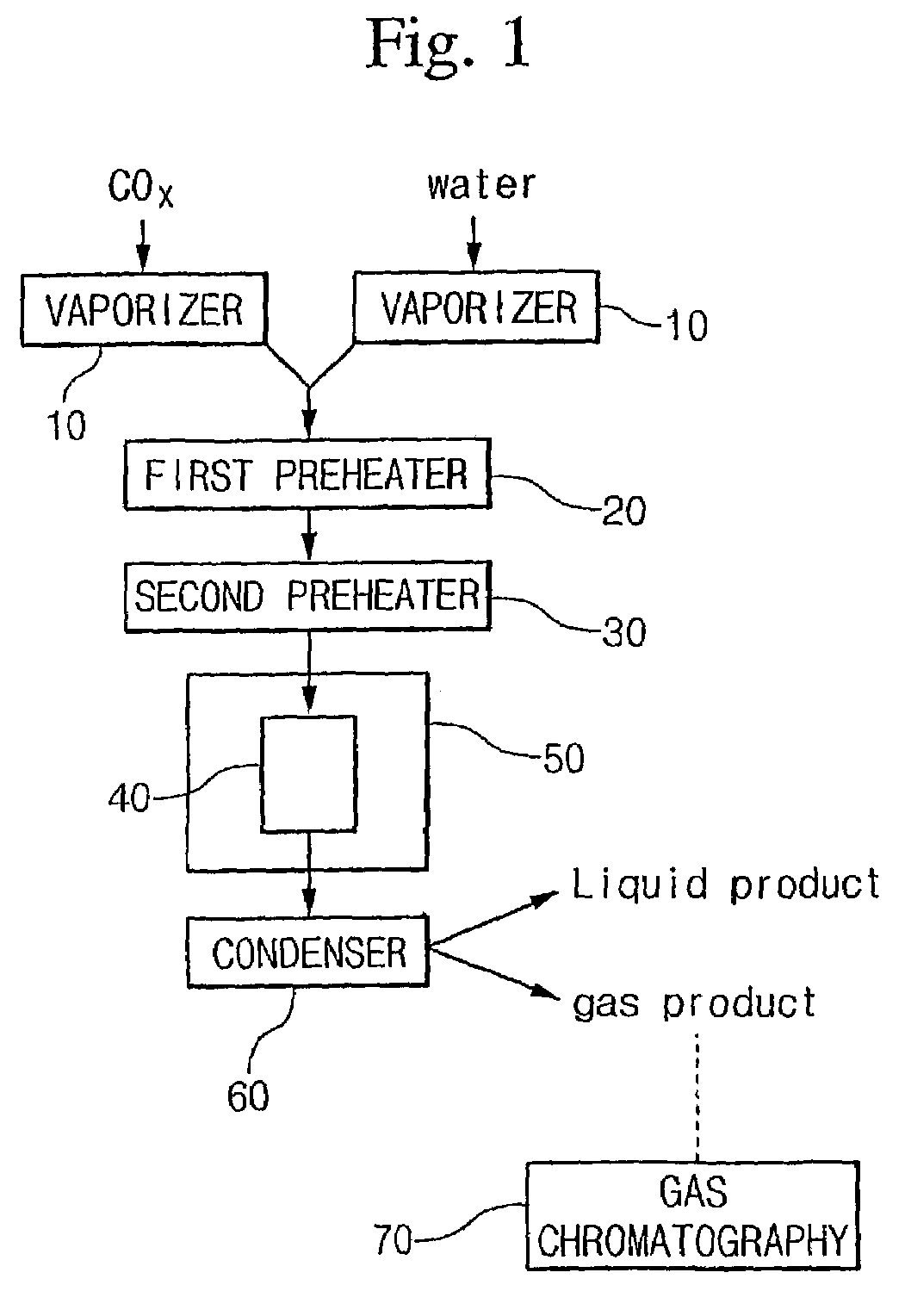
[0058]In the first embodiment, everything of the pyrolysis apparatus is the same but the quantity of condenser 60. A couple of condensers are connected to each other in series.

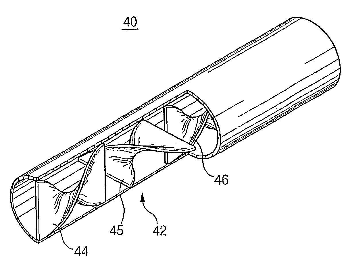
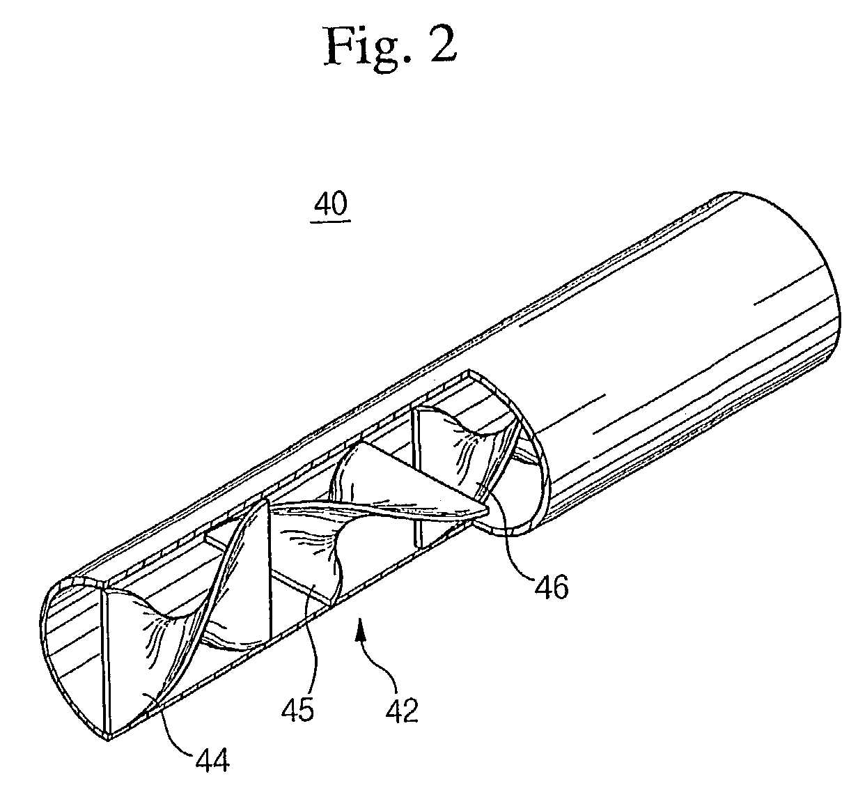
[0059]The pyrolysis is carried out by using the pyrolysis tube 40. With respect to the pyrolysis tube 40 including the mixer 42, its outside diameter and length are ⅜ inch and 60 cm, respectively.

[0060]According to the first embodiment, naphtha is used as a hydrocarbon, and its composition and properties are described in a table I.

[0061]

TABLE Ispecific gravity (g / cc)0.675initial boiling point (° C.)30.9final boiling point (° C.)160.7n-parafin (wt %)39.5l-parafin (wt %)38.9naphthene (wt %)15.3aromatic (wt %)6.3

[0062]The naphtha and water are inflowed into the pyrolysis apparatus. The naphtha is controlled to be twice as much as the water by weight, and the flow of naphtha is controlled to be 10 in LHSV.

[0063]The yield of the ethylene is calculated in accordance with the following equation I in the present ...

embodiment ii

[0067

[0068]The reaction conditions and experimental methods of the second embodiment are the same as those of the first embodiment, except the LHSV is 18. A table III shows the results of a pyrolysis experiment when the LHSV of naphtha is 18.

[0069]

TABLE IIIABinflowingnaphtha (cc / min)8.178.17amount ofwater (cc / min)2.762.76the reactantwater / naphtha in weight0.50.5LHSV, hr−1 (naphtha basis)1818reaction temp (° C.)880880yield of theH20.720.59productCO0.040.02(wt %)CO20.000.00CH410.77.8C2H427.021.7C3H616.614.8C2H4 + C3H643.636.5

embodiment iii

[0070

[0071]The reaction conditions and experimental methods of the third embodiment are the same as those of the second embodiment, except that the outer diameter of the pyrolysis tube is ½ inch. A table IV shows the results of the pyrolysis experiment.

[0072]

TABLE IVABinflowingnaphtha (cc / min)8.178.17amount ofwater (cc / min)2.762.76the reactantwater / naphtha in weight0.50.5LHSV, hr−1 (naphtha basis)1010reaction temp (° C.)880880yield of theH21.010.64productCO0.250.05(wt %)CO20.030.00CH414.99.2C2H434.423.9C3H615.312.8C2H4 + C3H649.736.7

[0073]The effect of using the pyrolysis tube including the mixer will be explained hereinafter.

[0074]As a result of mixing by the mixer in the pyrolysis tube, thermal transfer from the pyrolysis tube to the fluid flow is improved, the fluid flow is heated and mixed uniformly, and the stagnant flow of the fluid near the inner surface of the pyrolysis tube is removed, thereby preventing the hydrocarbons from over-cracking or undercracking.

[0075]Moreover, s...


PUM

PropertyMeasurementUnit
temperatureaaaaaaaaaa
velocityaaaaaaaaaa

Abstract

The present invention provides a pyrolysis tube for enhancing the yield of olefins and reducing a coking tendency in steam cracking of hydrocarbons. According to the present invention, the pyrolysis tube is characterized in that a plurality of mixing blades made by twisting two ends of a plate in opposite directions are included therein. The yield of ethylene is thereby improved and the coking tendency is reduced by mixing a fluid flow, improving a heat transfer rate and shortening a residence time of the reactants therein.

Description

[0001]This application is the national phase under 35 U.S.C. §371 of PCT International Application No. PCT / KR02 / 00387 which has an International filing date of Mar. 6, 2002, which designated the United States of America.BACKGROUND OF THE INVENTION[0002]1. Field of the Invention[0003]The present invention relates to pyrolysis of hydrocarbons, and especially to a pyrolysis tube for enhancing the yield of olefins and a pyrolysis method thereof.[0004]2. Description of the Related Art[0005]Steam cracking of hydrocarbons is a reaction to produce olefins such as ethylene and propylene by using naphtha, diesel and the like as a resource. The main ingredients of the naphtha, diesel and the like are paraffin-based hydrocarbons.[0006]The following conventional process is provided for steam cracking of hydrocarbons. The hydrocarbons and water are respectively vaporized, mixed together, and then the mixture thereof is preheated to about 600° C. In the next step, the mixture is decomposed thermal...

Claims


Application Information

Patent Timeline
Patent Type & Authority Patents(United States)
IPC IPC(8): C10G9/36B01F3/00B01F7/00C07C4/16B01F23/00C07C11/04C07C11/06C10G9/02C10G9/20
CPCC10G9/20C10G9/203Y10S585/922Y10S585/921C10G9/02
Inventor CHAE, JONG-HYUNLEE, WON-HOJEONG, SANG-MUNPARK, KEUN-HOO
Owner LG CHEM LTD
Why Eureka
Try Eureka