Device for detecting a position of a magnetic pole

a technology for detecting a device, which is applied in the direction of motor/generator/converter stopper, dynamo-electric converter control, instruments, etc., can solve the problem of not being able the position of a magnetic pole cannot be detected correctly, and the inability to adapt to the non-salient pole type spm motor. to achieve the effect o

Active Publication Date: 2007-01-30
FANUC LTD
View PDF13 Cites 13 Cited by
  • Summary
  • Abstract
  • Description
  • Claims
  • Application Information

AI Technical Summary

Benefits of technology

[0013]Accordingly, an object of the present invention is to provide a position-of-magnetic-pole detecting device capable of accurately detecting a position of a magnetic pole without the necessity of learning in advance a mechanical characteristic concerning friction or the properties of a motor (whether the motor is of a salient-pole type or non-salient-pole type, with or without magnetic saturation, or other properties.)
[0014]According to the first aspect of the present invention, a position-of-magnetic-pole detecting device for detecting a position of a magnetic pole in a rotor included in a synchronous motor comprises: a current command applying means for applying a current command in the direction of a predetermined excitation phase; a first position-of-magnetic-pole inferring means for inferring a position of a magnetic pole from the direction of rotation in which the motor rotates responsively to the current command; a voltage command applying means for applying a voltage command in the direction of the predetermined excitation phase; a second position-of-magnetic-pole inferring means for inferring the position of a magnetic pole from a fed-back current returned responsively to the voltage command; and a means for selecting either of the first and second position-of-magnetic-pole inferring means that infer the position of a magnetic pole. The first aspect is intended to prevent an event that a position of a magnetic pole cannot be detected because of a mechanical characteristic concerning friction or the like, and to make it possible to detect the position of a magnetic pole in a non-salient pole type synchronous motor. According to the second aspect of the present invention, a position-of-magnetic-pole detecting device comprises: a current command applying means for applying a current command in the direction of a predetermined excitation phase; a first position-of-magnetic-pole inferring means for inferring a domain, where the position of a magnetic pole lies and which has the width thereof determined with a range of electrical angles, from the direction of rotation in which the motor is rotated responsively to the current command, and an excitation phase, and narrowing the domain so as to infer the position of a magnetic position; a voltage command applying means for applying a voltage command in the direction of the predetermined excitation phase; a second position-of-magnetic-pole inferring means for inferring the orientation of a magnetic pole from a fed-back current returned responsively to the voltage command applied with an excitation phase changed sequentially, applying a voltage that causes magnetic saturation so as to determine the orientation of a magnetic pole, and inferring the position of a magnetic pole; and a means for selecting either of the first and second position-of-magnetic-pole inferring means that infer the position of a magnetic pole. The second aspect is intended to prevent an event that the position of a magnetic pole cannot be detected because of a mechanical characteristic concerning friction or the like, and to make it possible to detect the position of a magnetic pole in a non-salient-pole type synchronous motor.

Problems solved by technology

The methods described in the first to fourth patent documents for detecting a position of a magnetic pole by applying a voltage to a motor and detecting a current that flows through an armature can be adapted to the salient-pole type motor but cannot be adapted to the non-salient pole type SPM motor.
However, the method requires some motion of a rotor.
If the rotor makes no motion because of large friction of a machine, a position of a magnetic pole cannot be detected correctly.
However, the method utilizes the electric characteristic of the salient-pole type and magnetic saturation and cannot therefore be adapted to the non-salient pole type SPM motor.

Method used


Image

  • Device for detecting a position of a magnetic pole
  • Device for detecting a position of a magnetic pole
  • Device for detecting a position of a magnetic pole

Examples


Embodiment Construction

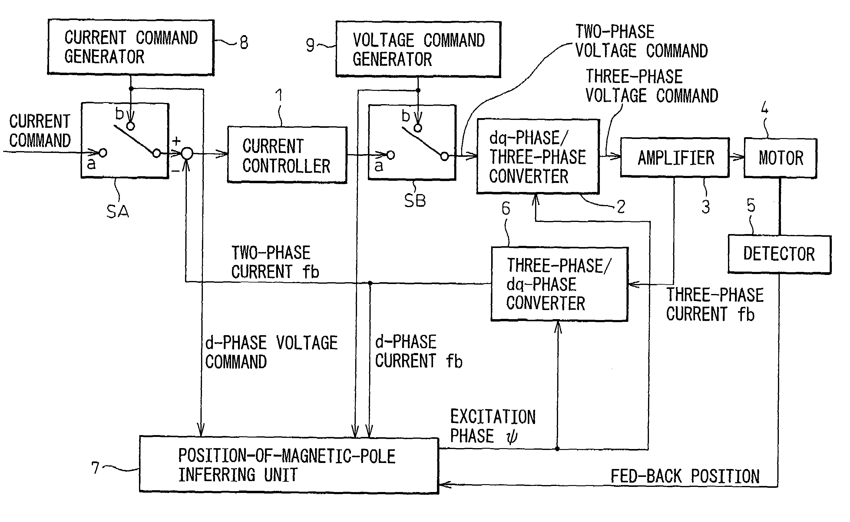
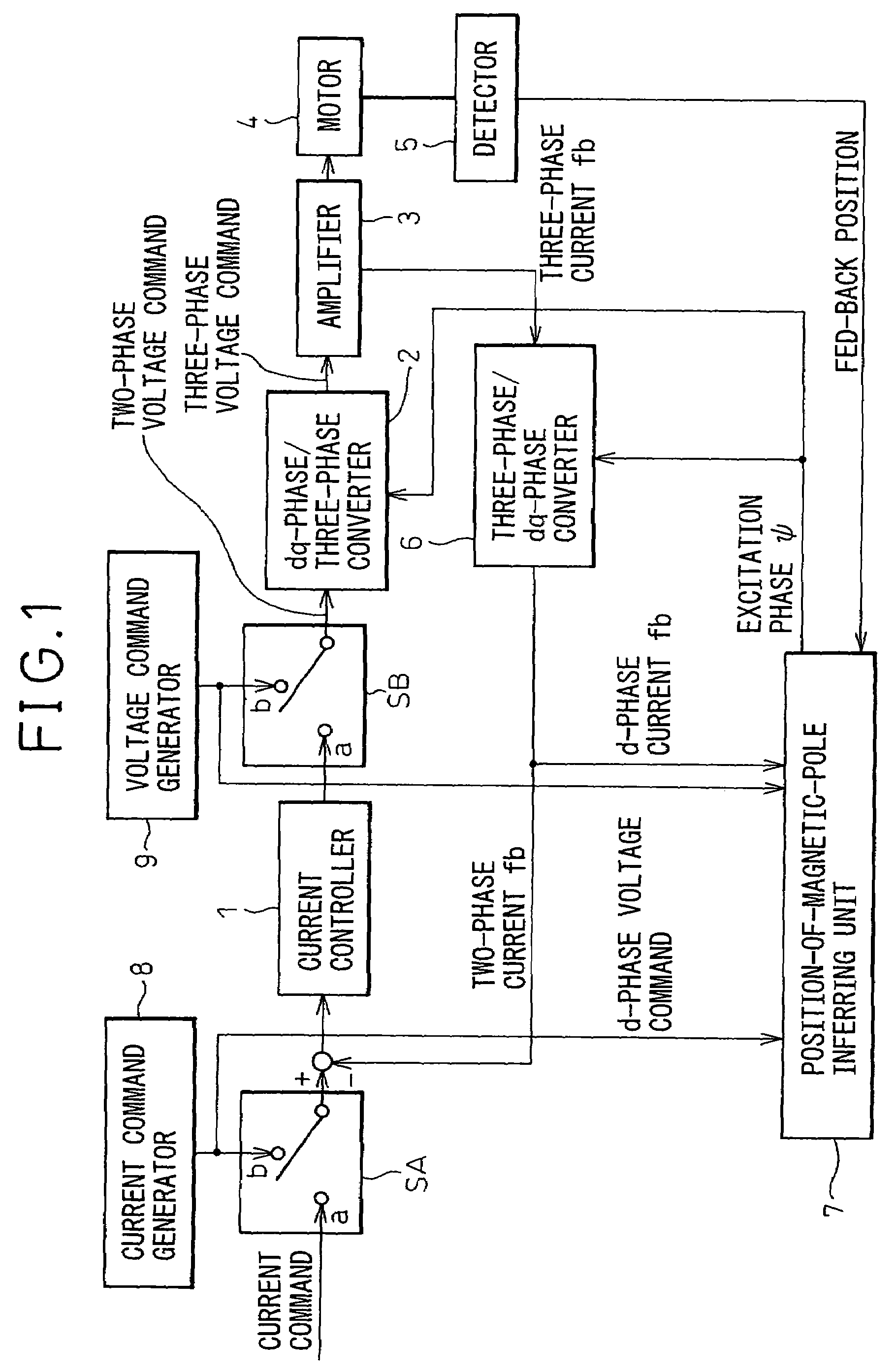
[0023]FIG. 1 is a block diagram of an embodiment of motor control equipment based on which a position-of-magnetic-pole detecting device in accordance with the present invention is realized. For normal driving and control of a motor, switches SA and SB have the contacts a thereof made. A converter 6 for converting a three-phase current into a dq-phase current converts a three-phase fed-back current into a dq-phase fed-back current. The d-phase and q-phase current components of the dq-phase fed-back current are subtracted from d-phase and q-phase current commands respectively, whereby deviations of the d-phase and q-phase current components are calculated. A current controller 1 performs feedback control on a current and issues a voltage command. Based on the position of a rotor included in the motor which is detected by a detector 5, a position-of-magnetic-pole inferring unit 7 calculates an excitation phase ψ. Based on the excitation phase, a converter 2 for converting a dq-phase vo...


PUM


Abstract

A position-of-magnetic-pole detecting device includes first and second units for inferring a position of a magnetic pole. The first unit applies a current command while changing an excitation phase, infers a domain, where the position of a magnetic pole lies and which has the width thereof determined with a range of electrical angles, from the direction of rotation in which a motor rotates, and the excitation phase, and reduces the domain so as to infer the position of a magnetic pole. The second unit infers the position of a magnetic pole from a fed-back current returned responsively to a voltage command applied with the excitation phase sequentially changed. Thereafter, a voltage high enough to cause magnetic saturation is applied in order to determine the orientation of a magnetic pole, whereby the position of a magnetic pole is inferred. Although the first unit is selected, if the motor does not move due to friction or the like, the second unit is used to infer the position of a magnetic pole. If the position of a magnetic pole inferred by the second unit differs from one value to another, the first unit is used to infer the position of a magnetic pole.

Description

BACKGROUND OF THE INVENTION[0001]1. Field of the Invention[0002]The present invention relates to detection of a position of a magnetic pole in a rotor included in a synchronous motor.[0003]2. Description of the Related Art[0004]In synchronous motors, a current is caused to flow through each of phase windings according to a position of a magnetic pole in a rotor for the purpose of generating a desired torque. An encoder or another sensor is used to detect the position of a magnetic pole in the rotor so that a current will flow in the direction of an appropriate excitation phase. This necessitates the employment of a sensor that is sensitive to an absolute value permitting detection of the position of a magnetic pole or the work of aligning a sensor with the position of a magnetic pole. In efforts to obviate the necessity of the employment of the sensor and the work of alignment, detection of the position of a magnetic pole is performed at the time of starting a motor.[0005]Various me...

Claims


Application Information

Patent Timeline
Patent Type & Authority Patents(United States)
IPC IPC(8): G01B7/30H02P6/16H02P1/46H02P6/06H02P6/08H02P6/18H02P6/182H02P6/185H02P6/28H02P21/00H02P21/14H02P21/18H02P21/22H02P21/24H02P21/28H02P21/34H02P23/14H02P25/08H02P27/04
CPCH02P1/46H02P6/16H02P6/183H02P21/146H02P6/20H02P2207/05H02P2203/11H02P21/18
Inventor TOYOZAWA, YUKIOSONODA, NAOTO
Owner FANUC LTD
Why Eureka
Try Eureka