Subsurface imagery for temperature measurement and fluid flow for oil recovery using electromagnetic impedance tomography (EMIT)

a technology of electromagnetic impedance tomography and subsurface imagery, which is applied in the direction of instruments, detection using electromagnetic waves, and borehole/well accessories, etc., can solve the problems of inability to take into account or take advantage of limited quality and utility of image created using current system and method, and inability to give a three-dimensional image over a large volume of conventional cross-borehole eit methods

Inactive Publication Date: 2007-01-30
KSN ENERGIES
View PDF3 Cites 21 Cited by
  • Summary
  • Abstract
  • Description
  • Claims
  • Application Information

AI Technical Summary

Benefits of technology

[0009]EMIT has several promising applications. For example, the present invention may be used to create high quality three-dimensional images in order to map subsurface water movement or mineral deposits. It may also be used to more effectively assist in the recovery of oil or gas, or in environmental remediation efforts.

Problems solved by technology

These methods do not take into account or take advantage of the fact that as resistivity changes with heating, the actual temperature of the fluids and other subsurface materials can be determined from such information.
Furthermore, the quality and utility of images created using current systems and methods is limited.
Conventional cross-borehole EIT methods do not give a three dimensional image over a large volume.

Method used


Image

  • Subsurface imagery for temperature measurement and fluid flow for oil recovery using electromagnetic impedance tomography (EMIT)
  • Subsurface imagery for temperature measurement and fluid flow for oil recovery using electromagnetic impedance tomography (EMIT)
  • Subsurface imagery for temperature measurement and fluid flow for oil recovery using electromagnetic impedance tomography (EMIT)

Examples


Embodiment Construction

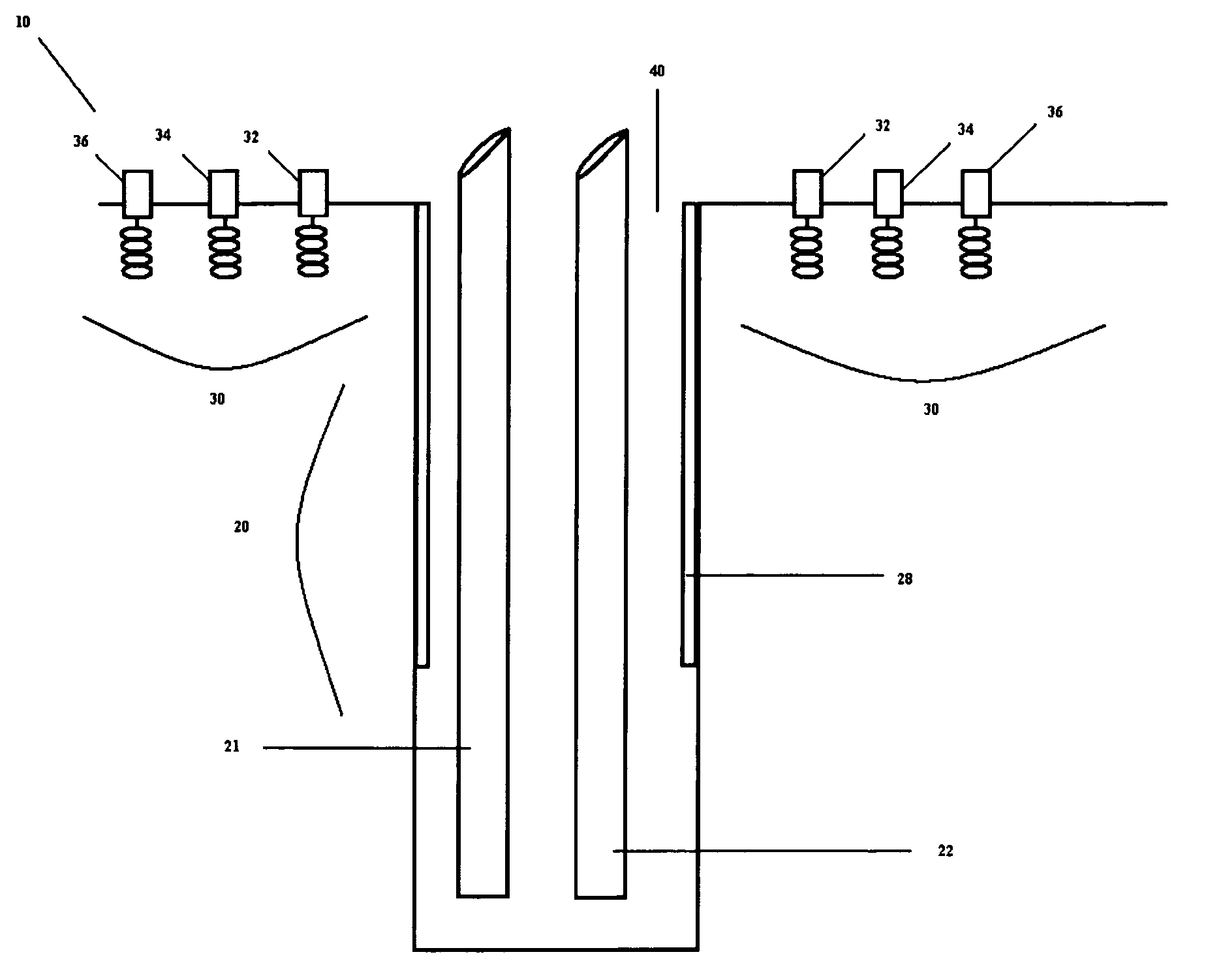
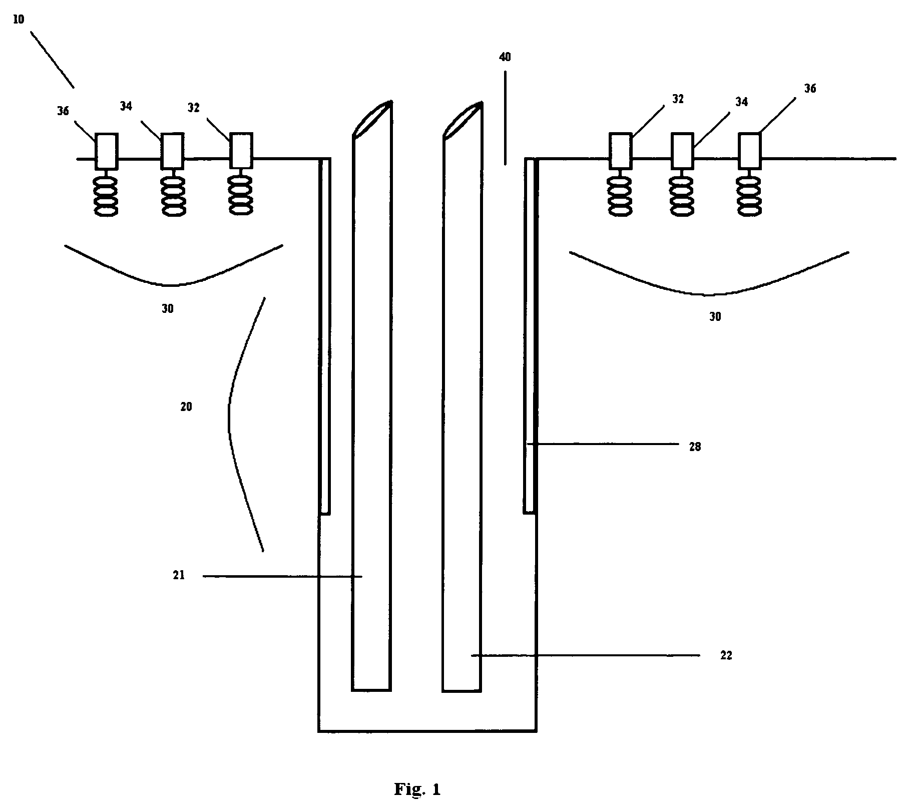
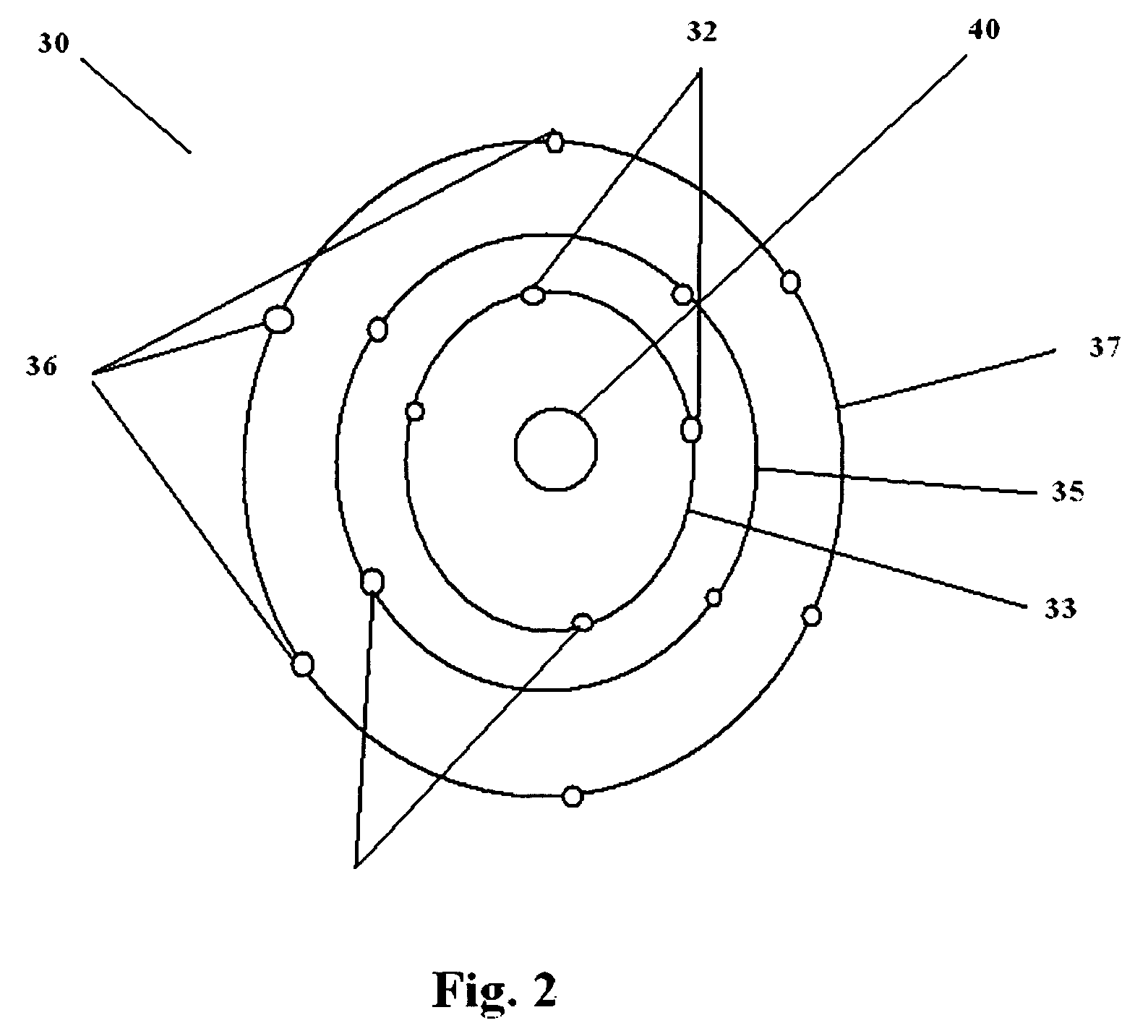
[0016]The dynamic tracking of subsurface fluid movement and three dimensional temperature measurement based on the change in resistivity or dielectric properties with temperature such as created by borehole selective radio frequency heating or steam drive in a reservoir of heavy crude oil can be provided by the principles of EMIT as described herein. This application requires a special arrangement of borehole and surface antenna structures sufficient in number and distribution to track the movement of the moving fluids during the application radio frequency heating or steam drive (“EMIT Antenna Array”). By providing generally circular arrays of magnetic and electric receiving elements consisting of concentric arrays of increasing diameter and a single transmitting borehole containing a solenoid-like antenna, real time tracking of the direction and spread of the hot fluids can be determined so as to optimize the oil recovery method. The arrangement of receivers on the surface need no...


PUM


Abstract

A new application of electromagnetic tomography is described directly related to the efficient recovery of oil and gas as well the removal of unwanted liquids from subsurface formations. The process involves the deployment of both surface and a single borehole magnetic dipole structures used for both transmitting and receiving low frequency electromagnetic energy. The surface antenna consists of circularly concentric arrays of small receiving solenoid antennas and the downhole system consists of one or more solenoid antenna in a single borehole. The concentricity of the surface array is centered about or in proximity to the borehole axis. The electromagnetic field radiated by the downhole antenna is received by each surface antenna. The amplitude and phase of voltages and currents received by each surface antenna is electronically processed based on the theoretical processing principles similar to what has been recently established for electromagnetic impedance tomography (EMIT). Several concentric surface antenna arrays with electronic switching between each circular array and the downhole solenoid will have the ability to image the spread and movement of oil and gas during thermal treatment and provide three dimensional temperature measurement. The oil movement to recovery wells may be provided by radio frequency heating or steam flood as in enhanced oil recovery. This information allows for developing very efficient oil and fluid recovery techniques by actually observing topographic images developed according to this invention.

Description

CROSS-REFERENCE TO RELATED APPLICATION(S)[0001]This application claims priority from U.S. provisional patent application No. 60 / 645,156, which was filed on Jan. 19, 2005, and which is incorporated herein by reference in its entirety.FIELD OF THE INVENTION[0002]The present invention generally relates to the use of electromagnetic impedance tomography (“EMIT”) to track subsurface fluid movement and provide three dimensional temperature measurement. More particularly, this invention relates to systems for using EMIT to create images of the spread and movement of oil and gas during thermal treatment and to provide three dimensional images over a large volume.BACKGROUND OF THE INVENTION[0003]There is a widespread need for images of subsurface conditions and materials in connection with various industrial applications. Such imaging can be used to map subsurface water movement or mineral deposits. It may also be sued to assist in the recovery of oil or gas, or in environmental remediation ...

Claims


Application Information

Patent Timeline
Patent Type & Authority Patents(United States)
IPC IPC(8): G01V3/08
CPCE21B43/24G01V3/30E21B47/002
Inventor KASEVICH, RAYMOND S.
Owner KSN ENERGIES
Why Eureka
Try Eureka