Method for operating a sliding gate, and sliding gate

Inactive Publication Date: 2007-01-30
STOPINC AG
View PDF2 Cites 10 Cited by
  • Summary
  • Abstract
  • Description
  • Claims
  • Application Information

AI Technical Summary

Benefits of technology

[0004]Based on the aforementioned it is a purpose of this invention to provide a method for operation of a sliding closure of the above ment

Problems solved by technology

Fireproof closure plates and fireproof sleeves utilized for these sliding closures, through which liquid steel smelt flows, as well as a mechanism supporting the same are subjected to relatively strong wear.
In reality, however, it has been proven that breakouts occur due to incorrect estimates or i

Method used


Image

  • Method for operating a sliding gate, and sliding gate
  • Method for operating a sliding gate, and sliding gate
  • Method for operating a sliding gate, and sliding gate

Examples


Embodiment Construction

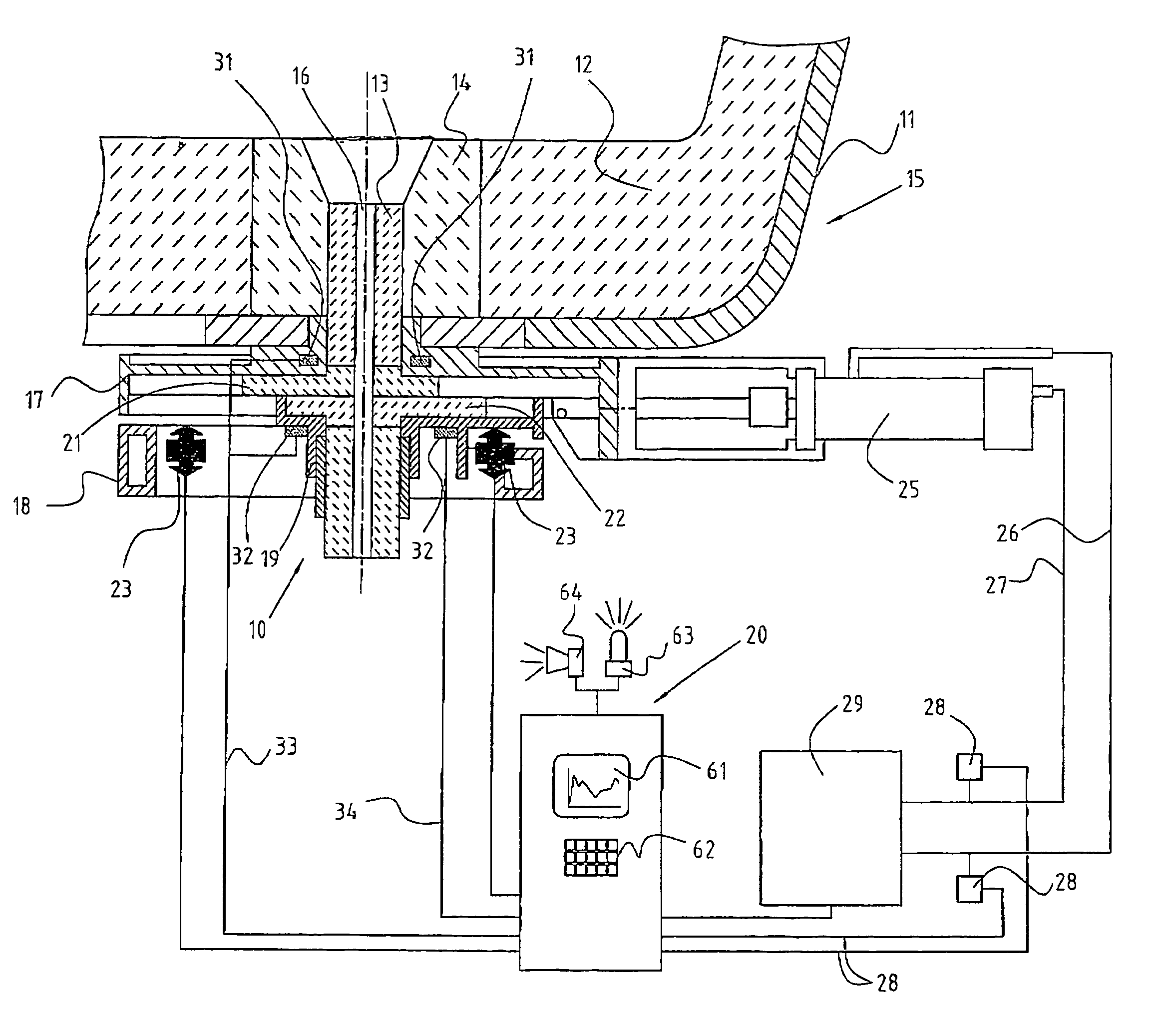
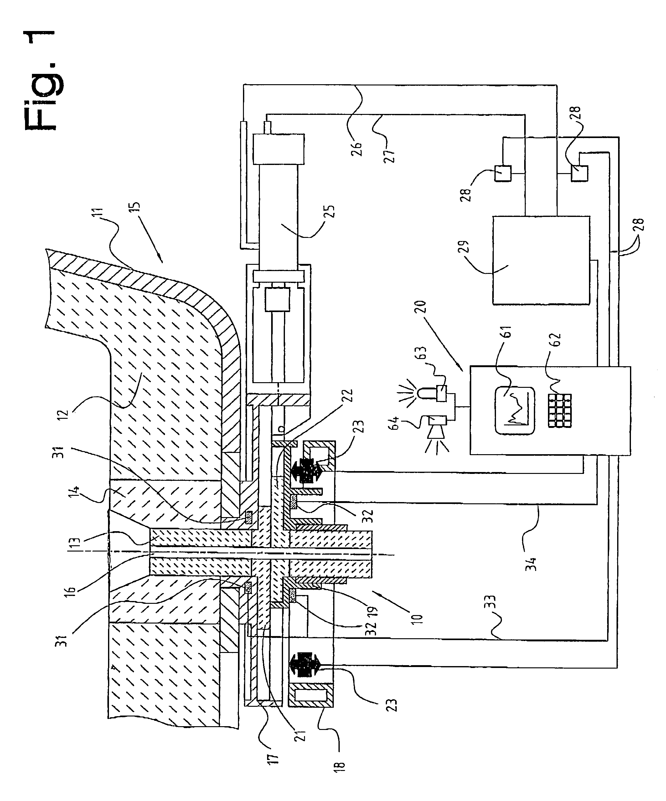
[0012]FIG. 1 shows a schematic illustration of a sliding closure 10 affixed to a metallurgical vessel 15 illustrated only in part, whereby the same consists, for example, of a pan of an extrusion molding plant containing steel smelt. As part of the vessel 15 a steel jacket 11, a fireproof cladding 12, a perforated stone 14, as well as a fireproof sleeve 13 with an outlet 16 are shown.

[0013]The sliding closure 10 incorporates an upper housing part 17 into which a fireproof closure plate 21 is affixed. Within a further housing part 19 a slideable closure plate 22 is held, whereby the housing part 19 is held within a housing frame 18 and can be moved by a drive member 25 into an open position—as illustrated—or into a closed position. This drive member 25 takes the form of a hydraulic piston / cylinder unit and is therefore activated via pipes 26, 27 by a hydraulic aggregate 29. In addition the closure plates 21, 22 are pressed against one another by spring elements 23, so that an adequat...


PUM

PropertyMeasurementUnit
Temperatureaaaaaaaaaa
Forceaaaaaaaaaa
Pressureaaaaaaaaaa

Abstract

A method is provided for operating a sliding closure for a metallurgical vessel. The sliding closure includes two tensionable fireproof closure plates opposing one another, with each of the two closure plates being slideably positioned within a corresponding housing part. Spring elements are provided for tensioning the closure plates, wherein one of the closure plates, along with its corresponding housing part, is slideable and can be moved into a closed or open position by a drive member. The method comprises: performing an offline and/or an online diagnosis of an operating condition within an area of the closure plates, by measuring at least one of size, temperature, pressure and force associated with the sliding closure so as to obtain at least one measured value, and evaluating the at least one measured value either directly or together with additional relevant process parameters; and based upon the diagnosis, either continuing use of the sliding closure or discontinuing use of the sliding closure.

Description

BACKGROUND OF THE INVENTION[0001]The invention concerns a method for operation of a sliding closure for metallurgic vessels, wherein the sliding closure incorporates at least opposingly tensionable fireproof closure plates which are each, slideably opposingly, positioned along glide surfaces within a housing part, wherein spring elements are envisaged for tensioning of the closure plates in at least one housing part, and wherein one closure plate with its housing part can be moved into a closed or open position by a drive member.[0002]Sliding closures are utilized especially for pans or distribution containers of extrusion molding plants for a controlled pouring of steel smelt. Fireproof closure plates and fireproof sleeves utilized for these sliding closures, through which liquid steel smelt flows, as well as a mechanism supporting the same are subjected to relatively strong wear. The plates and sleeves must therefore be replaced frequently.[0003]In order to achieve a high efficien...

Claims


Application Information

Patent Timeline
IPC IPC(8): B22D41/08B22D11/10B22D41/22B22D41/28B22D41/38
CPCB22D41/22B22D41/38B22D41/28
Inventor GERBER, PIERREBASLER, URS
Owner STOPINC AG
Why Eureka
Try Eureka