Fixed quantity supply equipment for inflators

a technology of supply equipment and inflators, which is applied in the direction of lighting and heating apparatus, packaging goods, combustion types, etc., can solve problems such as reducing workability, and achieve the effect of stable throughput and easy management of treatment operations

Active Publication Date: 2007-02-06
DAICEL CHEM IND LTD
View PDF5 Cites 1 Cited by
  • Summary
  • Abstract
  • Description
  • Claims
  • Application Information

AI Technical Summary

Benefits of technology

[0014]By making the bottom portions of the inflator accommodating chambers openable / closable, the inflators fall down naturally, so that a constant number of inflators can be supplied. Further, in the case of a system where inflators fall down naturally by opening the bottom portion in this manner, since inflators can be discharged irrespective of an accommodating state of the inflators, it becomes unnecessary to particularly consider the accommodating state of inflators inside the inflator accommodating chambers, which facilitates an accommodating work of the inflators.
[0020]According to the fixed quantity supply equipment for inflators of the present invention, a desired number of inflators can be supplied in a constant number mechanically. For this reason, since heat-treatment conditions for inflators can be maintained constant, management of a treatment operation is made easy and a stable throughput can be secured.

Problems solved by technology

When inflators which are subject to treatment are charged into the heat-treating tower, it is desirable to conduct charging by a mechanical means, because it is troublesome to conduct charging manually, which results in reduction of workability.

Method used


Image

  • Fixed quantity supply equipment for inflators
  • Fixed quantity supply equipment for inflators
  • Fixed quantity supply equipment for inflators

Examples


Embodiment Construction

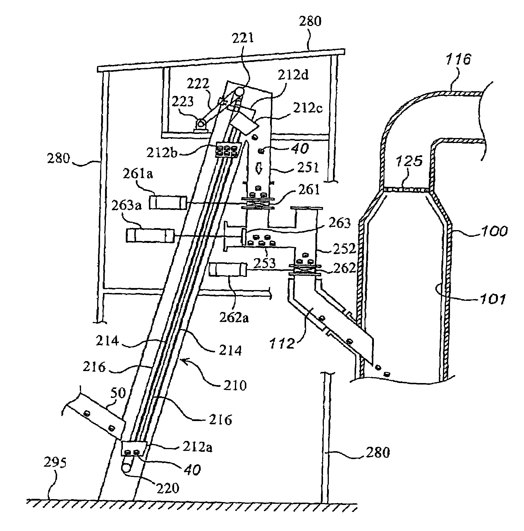
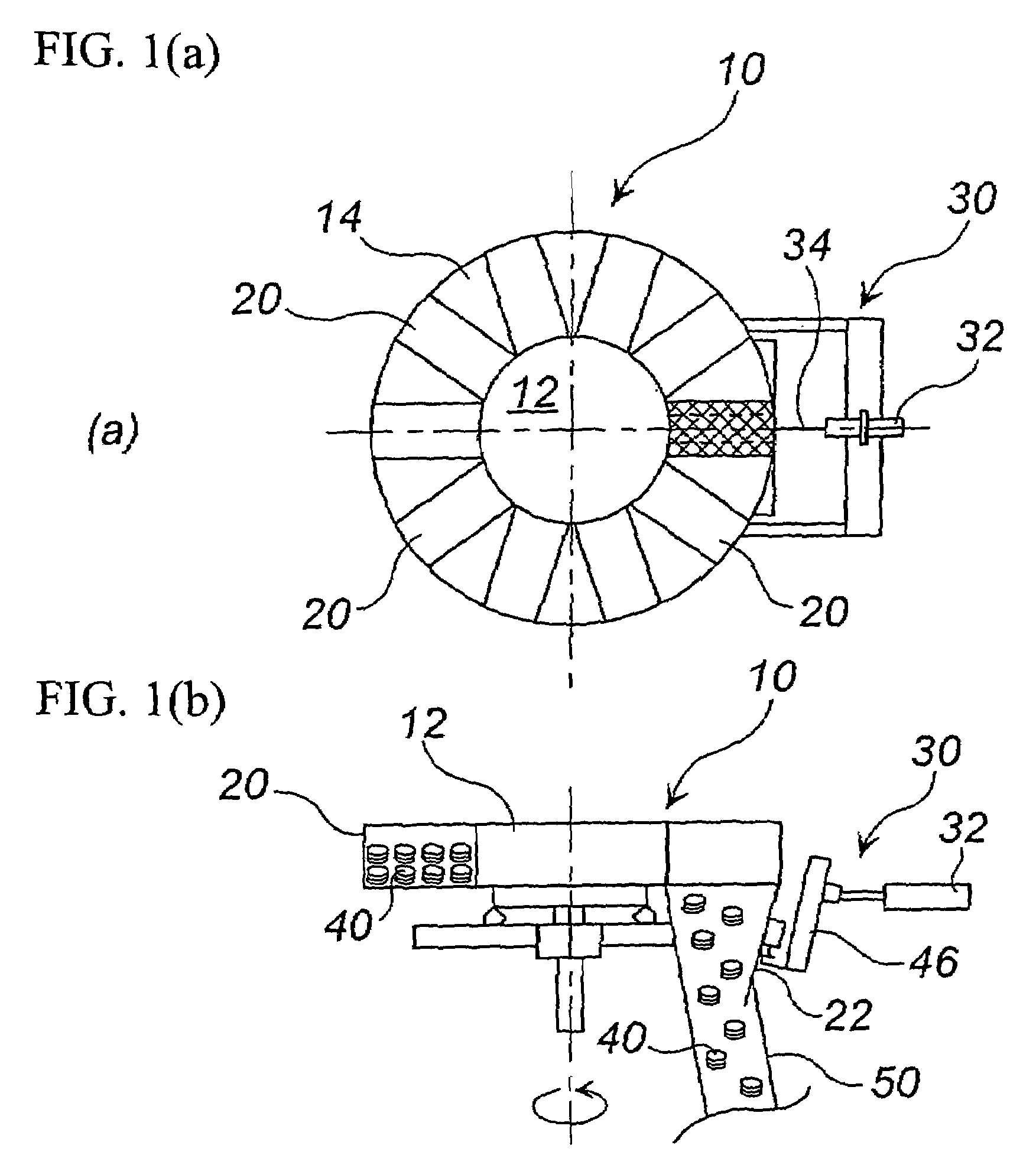
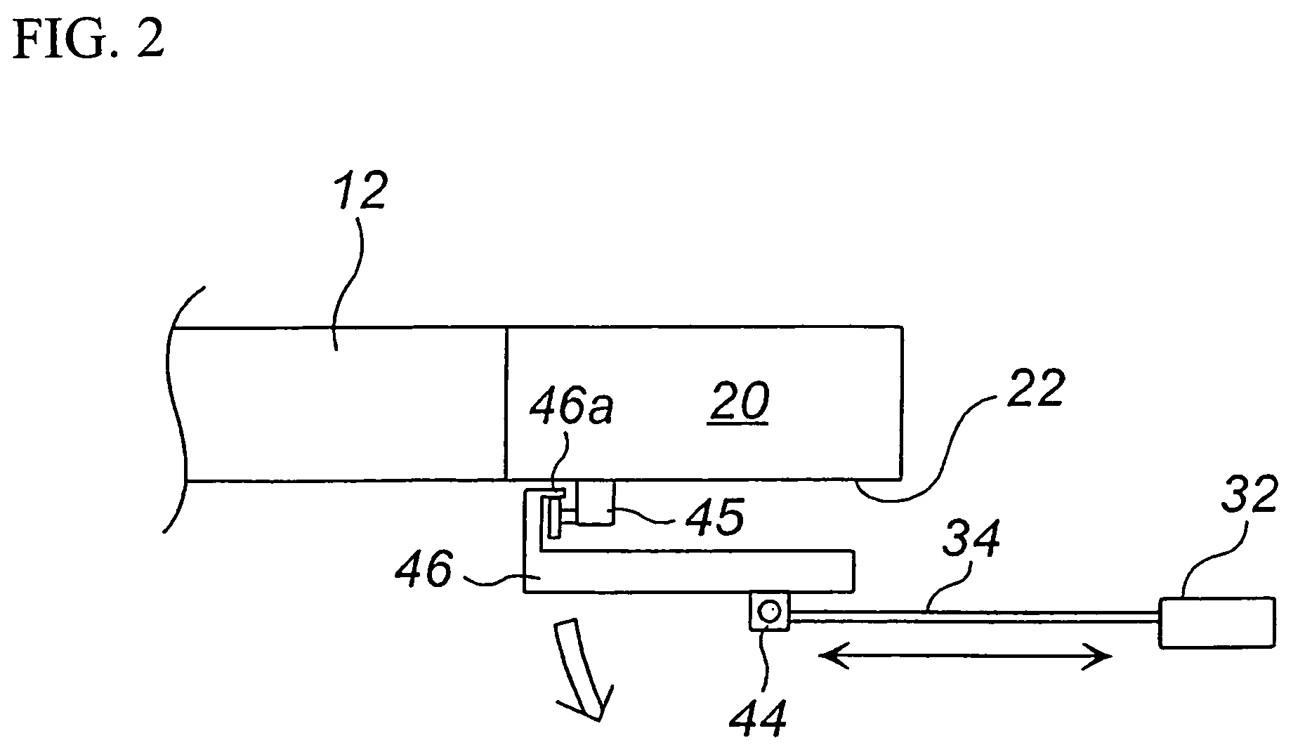
[0025]Hereinafter, an embodiment of the present invention will be explained with reference to the drawings. FIG. 1(a) is a plan view of a fixed quantity supply equipment for inflators, FIG. 1(b) is a front view of the apparatus in FIG. 1(a), and FIG. 2 is a partially enlarged view of the apparatus in FIG. 1.

[0026]A fixed quantity supply equipment 10 for inflators has a rotatable supporting shaft 12 connected to an unillustrated driving apparatus, an annular main body portion 14 integrally mounted at a periphery of the supporting shaft 12, inflator accommodating chambers 20 obtained by partitioning the annular main body portion 14 into a plurality of chambers, and an opening / closing means 30. The annular main body portion 14 rotates on an annular guide rail (not shown) partially cut off.

[0027]The inflator accommodating chamber 20 has a cubic shape, and its volume is determined in relation to a size of an inflator 40 and the total number of inflators 40 to be accommodated. In FIG. 1(a...


PUM

PropertyMeasurementUnit
timeaaaaaaaaaa
temperatureaaaaaaaaaa
workabilityaaaaaaaaaa

Abstract

A fixed quantity supply equipment for inflators is combined with a heat-treatment equipment for inflators. A bottom portion 22 of an inflator accommodating chamber 20 at a predetermined position is opened by an opening / closing means 30 utilizing pneumatics to cause inflators 40 inside the inflator accommodating chamber to fall naturally. Thereafter, the bottom portion 22 is closed, the bottom portion 22 of the next inflator accommodating chamber 20 is opened to cause inflators 40 inside the same to fall naturally. These actions are repeated to supply the inflators 40 in a constant number.

Description

[0001]This Nonprovisional application claims priority under 35 U.S.C. § 119(a) on Patent Application Nos. 2002-376024 and 2003-77054 filed in Japan on Dec. 26, 2002 and Mar. 20, 2003, the entire contents of which are hereby incorporated by reference.BACKGROUND OF THE INVENTION[0002]1. Field of the Invention[0003]The present invention relates to a fixed quantity supply equipment for inflators which is used in combination with a heat-treatment equipment for the inflators.[0004]2. Description of the Related Art[0005]Recently, since new cars equipped with an air bag(s) have increased, it is anticipated that a great deal of inflators accommodating gas generating materials will be seen when scrapping these cars. Therefore, from the viewpoint of safety and effective utilization of resources, it is necessary to ignite the gas generating materials by heat-treatment to safely recover metals and the like. Under such circumstances, a recovery / treatment system for inflators for an air bag is bei...

Claims


Application Information

Patent Timeline
Patent Type & Authority Patents(United States)
IPC IPC(8): B65B1/04B01J4/02B09B3/00B09B5/00B60R21/26B60R21/264B65G29/00B65G47/38F23G5/44F23G5/50F23G7/00
CPCB09B3/00B09B3/0083B09B5/00B65G29/00B65G47/38F23G5/448F23G5/50F23G7/003F23G7/005F23G5/442B60R21/2644F23G2900/7001F23G2205/16F23G2207/20B09B3/40
Inventor AOYAMA, KEISHINAKAZAWA, YUJI
Owner DAICEL CHEM IND LTD
Why Eureka
Try Eureka