Fuel injection valve for internal combustion engines with damping chamber reducing pressure oscillations

a technology of internal combustion engine and damping chamber, which is applied in the direction of fuel injection apparatus, fuel injection with fuel accumulator, charge feed system, etc., can solve the problems of inability to accurately measure and inject, and inability to achieve accurate instant injection, etc., and achieve static pressure level and fade of pressure fluctuations.

Inactive Publication Date: 2007-02-06
ROBERT BOSCH GMBH
View PDF10 Cites 1 Cited by
  • Summary
  • Abstract
  • Description
  • Claims
  • Application Information

AI Technical Summary

Benefits of technology

[0007]The fuel injection valve of the present invention has the advantage over the prior art that accurately defined injection events in rapid succession are made possible. Pressure fluctuations that occur in the region of the pressure chamber and hence in the immediate vicinity of the injection openings are damped, so that very quickly after the closing event of the fuel injection valve, a static state is again achieved in the pressure chamber. To that end, the pressure chamber communicates with a damping chamber, embodied in the housing, via at least one throttle disposed in the housing. If pressure changes occur in the region of the pressure chamber, of the kind caused for instance by the opening or closure of the valve member, then a higher or lower fuel pressure than in the damping chamber prevails in the pressure chamber. Because of this pressure drop, fuel will flow through the throttle, either from the pressure chamber into the damping chamber or from the damping chamber into the pressure chamber and will thus bring about a pressure equalization between the damping chamber and the pressure chamber. Since the fuel flowing back and forth has to pass through the throttle, these pressure fluctuations are damped by friction losses at the throttle, so that fading of these pressure fluctuations is very rapid, and a static pressure level in the pressure chamber is rapidly achieved.
[0008]In an advantageous embodiment of the subject of the invention, the damping chamber is embodied as a blind bore embodied in the housing of the fuel injection valve. The blind bore discharges directly into the pressure chamber here, and the throttle is preferably located close to the pressure chamber. Because the damping chamber is embodied as a blind bore, the damping chamber in the housing can be produced simply and economically.
[0009]In a further advantageous feature, more than one throttle is disposed in the throttle and forms the communication passage between the damping chamber and the pressure chamber. As a result, the damping action of the throttles can be boosted, and by means of different throttles, better adaptation to the requirements of the fuel injection valve can be achieved.
[0010]In another advantageous feature of the subject of the invention, the valve member is disposed in a valve body, while the damping chamber is embodied in a valve holding body, and both the valve body and the valve holding body are part of the housing. Between the valve body and the valve holding body there is a shim, through which the communication passage from the pressure chamber to the damping chamber extends. The throttle is disposed in the shim, so that by replacing the shim with a shim that has a different sized throttle, easy replacement of the throttle and hence an adaptation of the damping action to various fuel injection valves is possible, without having to change the construction of the fuel injection valve otherwise.

Problems solved by technology

Because of the very fast closing events of the valve member, which are completed within a range of only a few milliseconds, pressure fluctuations occur in the pressure chamber both upon opening and upon closure of the fuel injection valve and lead on the one hand to severe mechanical stresses on the housing and on the other to an indefinite pressure state at the injection openings at the beginning of the next injection, so that the following injection begins at a state that is not precisely defined, making accurate metering and an accurate instant of injection impossible.
Especially in injection events that are broken down into a preinjection, main injection and / or postinjection, this is a problem, since modern fuel injection systems react very sensitively to fluctuations in quantity upon injection.
In this fuel injection valve as well, especially at the onset and end of the injection event, pressure fluctuations occur in the region of the pressure chamber, where they can lead to mechanical stresses, and if the fluctuations persist can lead to an undefined state at the onset of the next injection and can impair the quality of subsequent injections.

Method used


Image

  • Fuel injection valve for internal combustion engines with damping chamber reducing pressure oscillations
  • Fuel injection valve for internal combustion engines with damping chamber reducing pressure oscillations
  • Fuel injection valve for internal combustion engines with damping chamber reducing pressure oscillations

Examples


Embodiment Construction

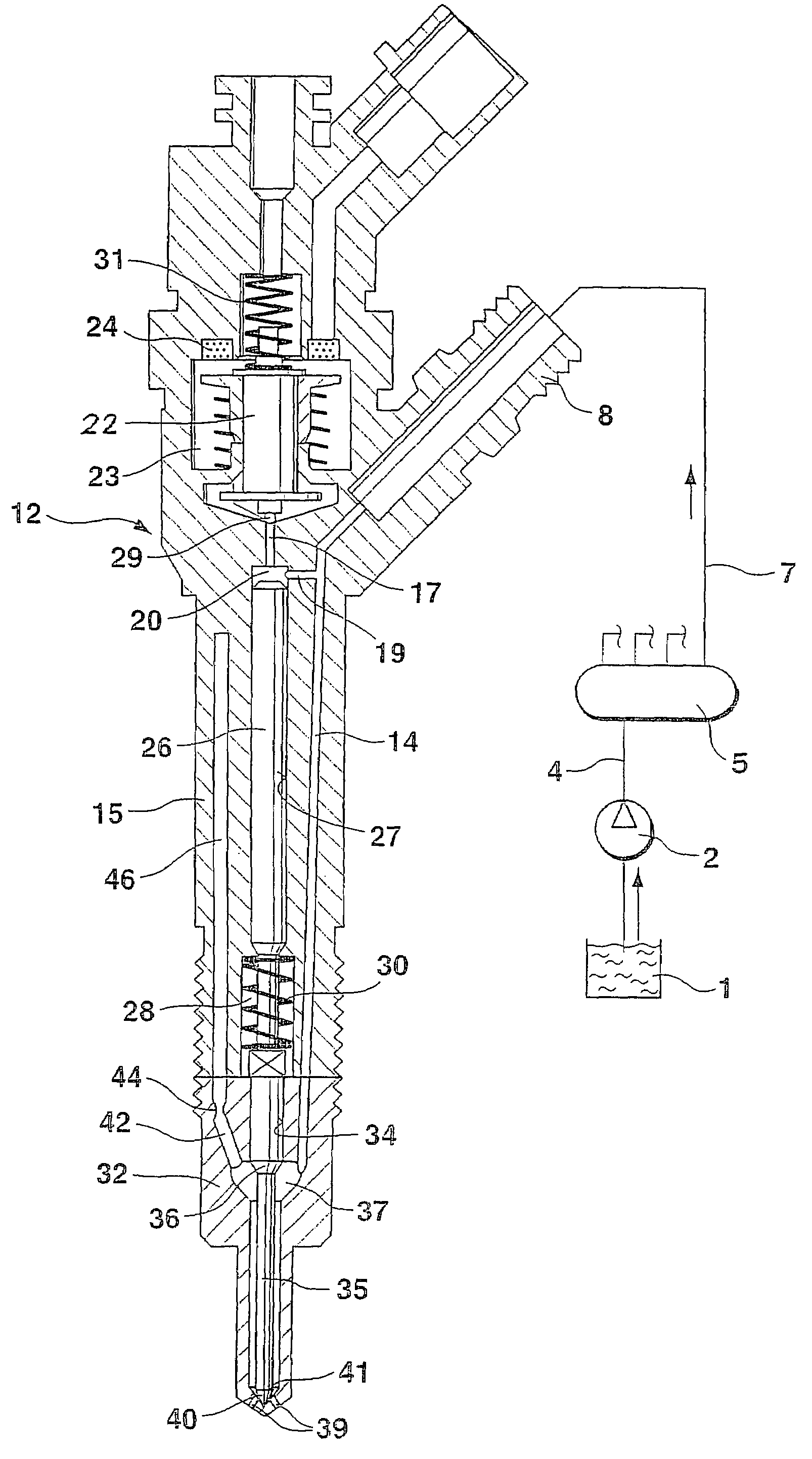
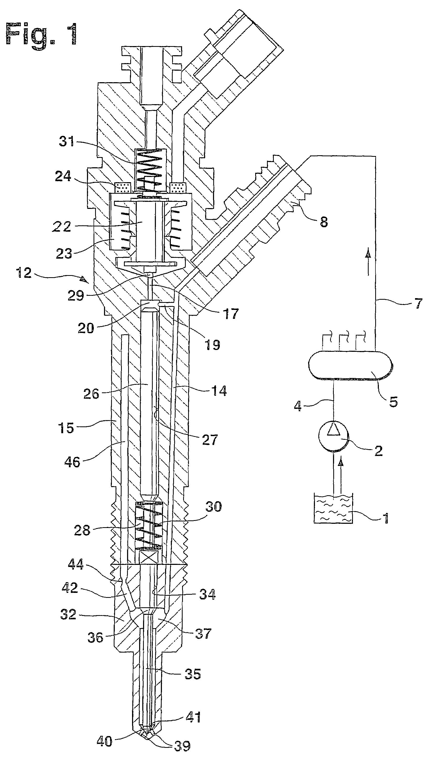
[0014]In FIG. 1, a longitudinal section through a fuel injection valve of the invention is shown, along with the schematically illustrated high-pressure fuel supply. The fuel injection valve has a housing 12, which includes a valve holding body 15 and a valve body 32. A bore 34 is embodied in the valve body 32, and a pistonlike valve member 35 is disposed longitudinal displaceably in this bore. In a portion remote from the combustion chamber, the valve member 35 is guided sealingly in the bore 34, and it tapers toward the combustion chamber, forming a pressure shoulder 36. At the level of the pressure shoulder 36, a pressure chamber 37 is embodied in the valve body 32 by means of an enlargement of the bore 34; this pressure chamber continues in the form of an annular conduit, surrounding the valve member 35, as far as the end toward the combustion chamber of the bore 34. With its end toward the combustion chamber, the valve member 35 controls the opening of at least one injection op...


PUM


Abstract

A fuel injection valve for internal combustion engines, having a housing (12; 48) in which a pistonlike valve member (35; 60) is disposed longitudinally displaceably in a bore (34; 57). The valve member (35; 60) is surrounded, over at least part of its length, by a pressure chamber (37; 68), embodied in the housing (12; 48), that can be filled with fuel at high pressure; the valve member (35; 60) controls the communication of the pressure chamber (37; 68) with at least one injection opening (39; 66). The pressure chamber (37; 68) communicates with a damping chamber (46; 80), embodied in the housing (12; 48), via at least one throttle (44; 78) disposed in the housing (12; 48), so that pressure fluctuations that occur in the damping chamber (46; 60) rapidly fade (FIG. 1).

Description

CROSS-REFERENCE TO RELATED APPLICATIONS[0001]This application is a 35 USC 371 application of PCT / DE 02 / 01037 filed on Mar. 22, 2002.BACKGROUND OF THE INVENTION[0002]1. Field of the Invention[0003]The invention is directed to an improved fuel injection valve for internal combustion engines.[0004]2. Description of the Prior Art[0005]Various versions of fuel injection valves of the type with which this invention is concerned are known from the prior art. For instance, in German Patent Disclosure DE 196 50 865 A1, a fuel injection valve is described that is in constant communication with a common rail in which fuel at high pressure is furnished. The fuel injection valve has a housing in which a valve member is disposed longitudinally displaceably in a bore; by its longitudinal motion, this valve member controls the opening of at least one injection opening, through which fuel from a pressure chamber surrounding the valve member is injected into the combustion chamber of the engine. Beca...

Claims


Application Information

Patent Timeline
Patent Type & Authority Patents(United States)
IPC IPC(8): F02M61/20F02M45/12F02M47/00F02M47/02F02M61/10F02M61/16F02M63/00
CPCF02M47/027F02M61/16F02M2200/40F02M2200/315F02M61/165
Inventor EGLER, WALTERBOEHLAND, PETERKANNE, SEBASTIAN
Owner ROBERT BOSCH GMBH
Why Eureka
Try Eureka