
Spiral type seawater desalination apparatus

a seawater desalination and spiral-type technology, applied in the direction of membranes, reverse osmosis, water treatment parameter control, etc., can solve the problems of high maintenance costs, difficulty in obtaining water quality as high as that obtained, and low production efficiency so as to increase the production efficiency of seawater desalination, reduce the fluctuation of reverse osmosis membrane elements housed in a single pressure vessel, and reduce the effect o

Inactive Publication Date: 2016-02-11
MITSUBISHI HEAVY IND LTD
View PDF0 Cites 0 Cited by
  • Summary
  • Abstract
  • Description
  • Claims
  • Application Information

AI Technical Summary

Benefits of technology

This configuration reduces fluctuation among reverse osmosis membrane elements, increases production efficiency, prolongs membrane life, and reduces the number of pressure vessels needed, while maintaining effective operation with up to ten elements in a single vessel.

Problems solved by technology

However, the reverse osmosis method has such problems that a careful pretreatment (a treatment using “an ultrafiltration membrane (UF membrane)” or “a microfiltration membrane (MF membrane)” that reduces a turbid content in seawater that is raw water) is required so as not to clog the RO membrane with microorganisms and deposits in seawater, and that maintenance or the like is costly.
The reverse osmosis method has difficulty to obtain water quality as high as that obtained by the evaporation method.

Method used


Image

  • Spiral type seawater desalination apparatus
  • Spiral type seawater desalination apparatus
  • Spiral type seawater desalination apparatus

Examples


first embodiment

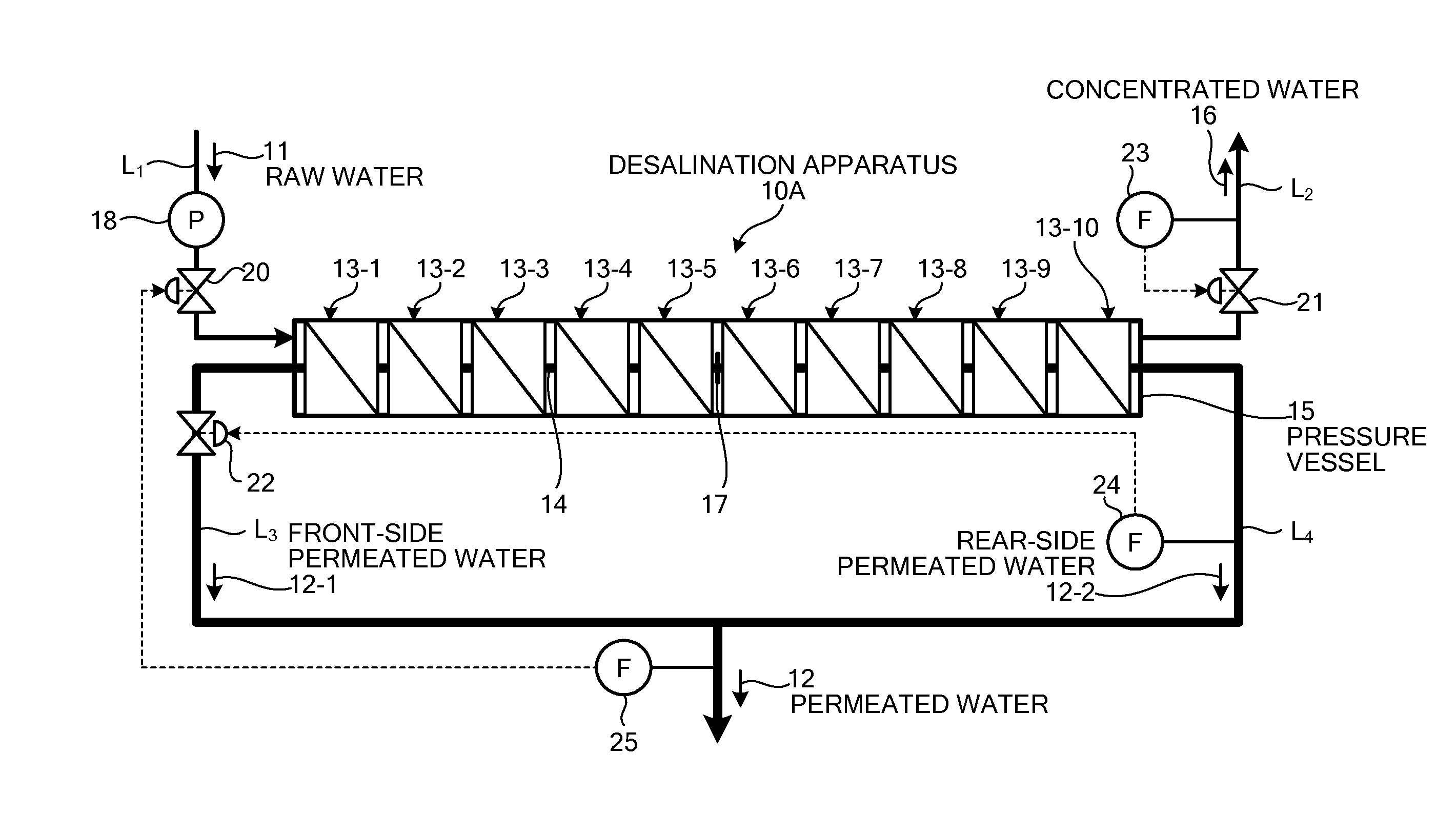
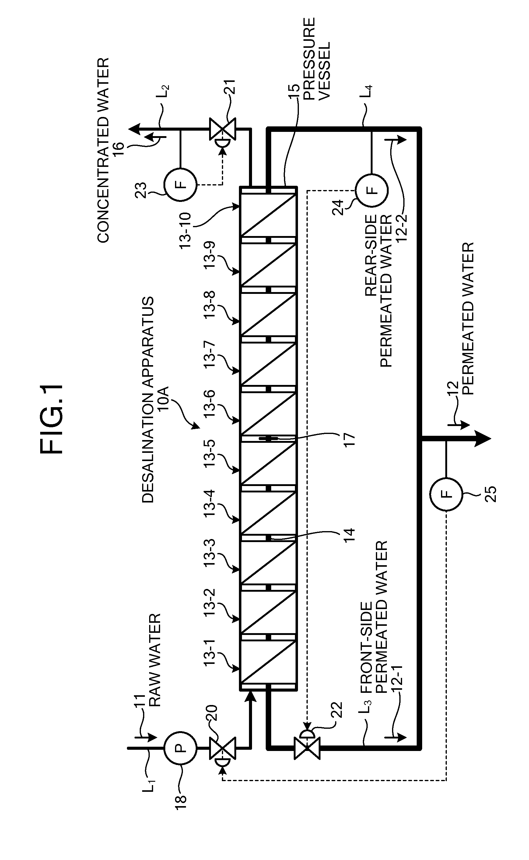
[0041]A spiral type seawater desalination apparatus according to an embodiment of the present invention will be described with reference to the accompanying drawings. FIG. 1 is a schematic of a spiral type seawater desalination apparatus according to a first embodiment.

[0042]As shown in FIG. 1, a spiral type seawater desalination apparatus (desalination apparatus) 10A includes: a spiral type pressure vessel (pressure vessel) 15 in which a plurality of reverse osmosis membrane apparatuses (hereinafter, “desalination elements” or “elements”) 13-1 to 13-10 having spiral reverse osmosis membranes (RO membranes) to obtain permeated water 12 that is fresh water by reducing a salt content from raw water (seawater) 11 that is supplying water, is connected through a permeated water pipe 14, and is housed in a connected state; a raw water supplying line L1 through which the raw water 11 is supplied into the pressure vessel 15; a concentrated water discharging line L2 through which concentrate...

second embodiment

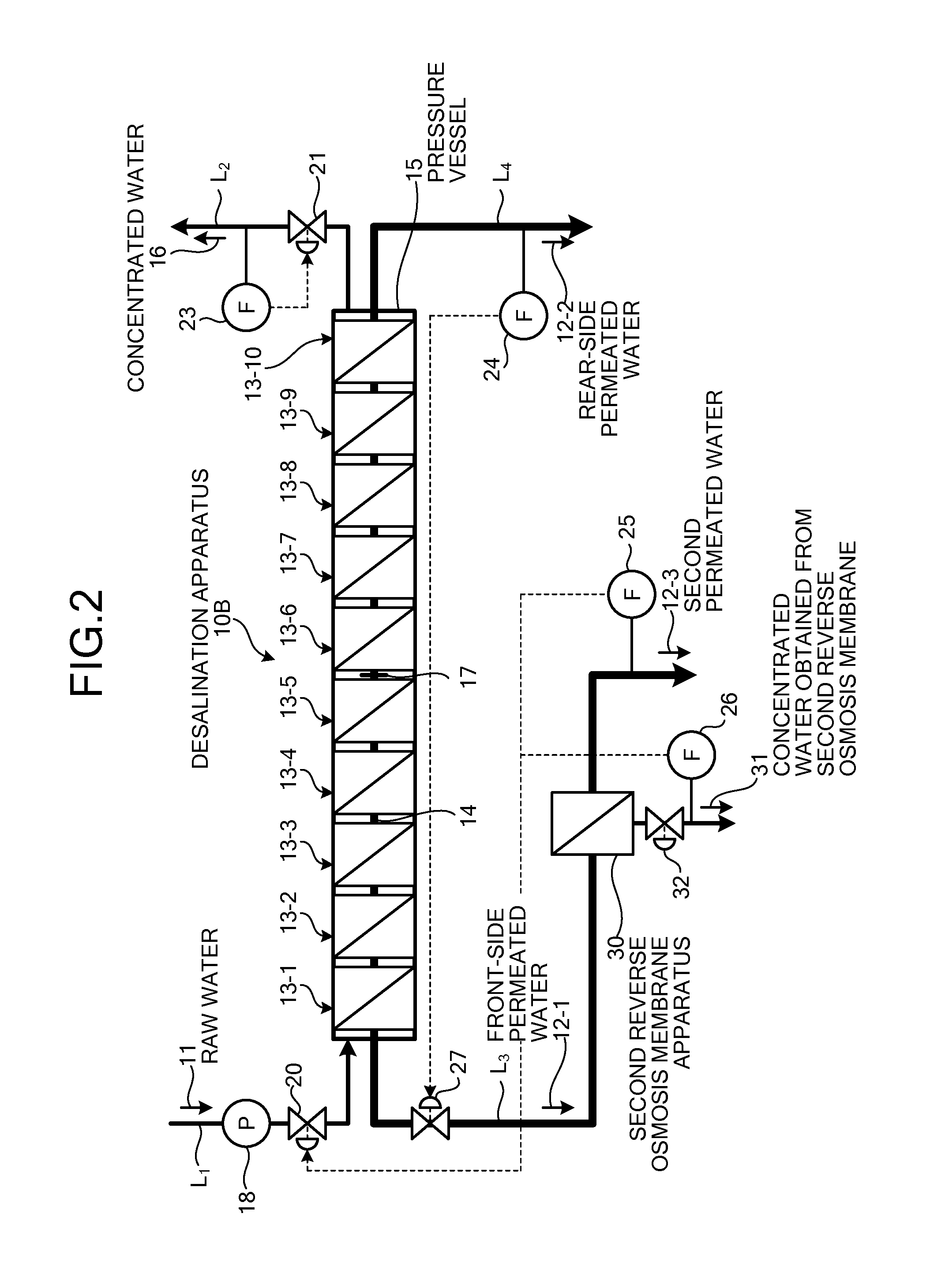
[0053]A spiral type seawater desalination apparatus according to an embodiment of the present invention will be described with reference to the accompanying drawings. FIG. 2 is a schematic of a spiral type seawater desalination apparatus according to a second embodiment.

[0054]As shown in FIG. 2, a spiral type seawater desalination apparatus 10B includes, in addition to the apparatus shown in FIG. 1, a second reverse osmosis membrane apparatus 30 that is mounted in the front-side permeated water line L3 and provides second permeated water 12-3 using the front-side permeated water 12-1 with a high pressure (15 kg / cm2). In the figure, numeral 26 denotes a flowmeter, 31 denotes the concentrated water obtained from the second reverse osmosis membrane, and 32 denotes a flow regulating valve that regulates the flow rate of the concentrated water obtained from the second reverse osmosis membrane. A first reverse osmosis membrane apparatus relative to the second reverse osmosis membrane appa...

third embodiment

[0061]A spiral type seawater desalination apparatus according to an embodiment of the present invention will be described with reference to the accompanying drawings. FIG. 3 is a schematic of a spiral type seawater desalination apparatus according to a third embodiment.

[0062]As shown in FIG. 3, a spiral type seawater desalination apparatus 10C includes, in addition to the apparatus shown in FIG. 1, an energy recovery apparatus 41 that is mounted in the front-side permeated water line L3 and recovers the energy of the front-side permeated water 12-1 with a high pressure (15 kg / cm2).

[0063]The front-side permeated water 12-1 has a high pressure (15 kg / cm2), so that the energy recovery apparatus 41 utilizes pressure energy effectively.

[0064]The energy recovery apparatus 41 is installed in the front-side permeated water line L3 connected to the front elements 13-1 to 13-5 from which the permeated water 12 is obtained readily. The recovered energy can be utilized for, for example, the ope...


PUM

PropertyMeasurementUnit
concentrationaaaaaaaaaa
pressureaaaaaaaaaa

Abstract

An embodiment of the present invention includes: a spiral type pressure vessel 15 in which a plurality of reverse osmosis membrane apparatuses 13-1 to 13-10 having spiral reverse osmosis membranes is connected through a permeated water pipe 14, and is housed in a connected state; a raw water supplying line that supplies raw water 11 into the pressure vessel 15; a concentrated water discharging line through which concentrated water 16 concentrated is discharged; a plug 17 that blocks the permeated water pipe 14 at the center of the reverse osmosis membrane apparatuses 13-1 to 13-10; a front-side permeated water line and a front-side permeated water line through which front-side permeated water 12-1 and rear-side permeated water 12-2 are discharged to the exterior, respectively, which are separated fore and aft, respectively, of the permeated water pipe 14 blocked by the plug 17; a pressure regulating valve 20 that is mounted in the raw water supplying line and regulates the supply pressure of the raw water 11; and a flow regulating valve 22 that is mounted in the front-side permeated water line and regulates the pressure of the front-side permeated water 12-1.

Description

CROSS-REFERENCE TO RELATED APPLICATION[0001]This application is a divisional of U.S. application Ser. No. 13 / 148,416 filed on Aug. 8, 2011, which is a National Stage Application of PCT / JP2009 / 064059 filed on Aug. 7, 2009, which is based on and claims benefit of priority from Japanese Patent Application No. 2009-026627 filed on Feb. 6, 2009, the entire contents of which are incorporated herein by reference in their entirety.TECHNICAL FIELD[0002]The present invention relates to a spiral type seawater desalination apparatus capable of reducing the fluctuation in reverse osmosis membrane elements housed in a pressure vessel.BACKGROUND ART[0003]An evaporation method by which seawater is evaporated, and a reverse osmosis method by which seawater is pressurized to pass through a type of a filtration membrane called a reverse osmosis membrane (RO membrane) to filter fresh water while the salt content of the seawater is concentrated and discharged, have been used as conventional methods to o...

Claims


Application Information

Patent Timeline
Patent Type & Authority Applications(United States)
IPC IPC(8): B01D63/12B01D61/02C02F1/44
CPCB01D63/12B01D61/025C02F1/441B01D2313/18C02F2303/10B01D2311/14B01D2311/16B01D2319/025C02F2103/08B01D2313/246B01D61/06B01D2317/025B01D2319/022C02F2209/03B01D61/12B01D2311/165B01D2317/022Y02W10/30Y02A20/131B01D61/026
Inventor ITOTAKEUCHI, KAZUHISAHORI, TAKAYOSHITANAKA, KENJIIWAHASHI, HIDEO
Owner MITSUBISHI HEAVY IND LTD
Learn More