Endoscope system using normal light and fluorescence

a technology of endoscope and fluorescence, which is applied in the field of endoscope system using normal light and fluorescence, can solve the problems of insufficient identification function between normal tissue and pathologically affected tissue, difficult identification of pathologically affected tissue and normal tissue in some cases, etc., and achieves the effect of simple configuration and easy identification of normal tissue and pathologically

Inactive Publication Date: 2007-02-06
OLYMPUS CORP
View PDF19 Cites 49 Cited by
  • Summary
  • Abstract
  • Description
  • Claims
  • Application Information

AI Technical Summary

Benefits of technology

[0023]It is an object of the present invention to provide an endoscope system which can obtain images for easily identifying normal tissue and pathologically affected tissue with a simple configuration.
[0024]It is another object of the present invention to provide an endoscope system which allows observing both normal-light images and fluorescent images.
[0025]The present invention is an endoscope system comprising a light source for illuminating illumination light having two different wavelength bands and excitation light for exciting fluorescence; image capturing means for capturing two reflected light images by reflected light when the illumination light is irradiated onto a biological tissue and is reflected, and a fluorescent image by fluorescence excited by the excitation light; image processing means for processing the two reflected light images and a fluorescent image and a creating processed image; and display means for displaying the processed imag...

Problems solved by technology

In the first prior art, the intensity of the fluorescence emitted from a normal tissue differs depending on the patient, so the color tone of a normal tissue differs depending on the patient, and the identification of pathologically affected tissue and normal tissue may be difficult in some cases.
In the third prior art, a re...

Method used


Image

  • Endoscope system using normal light and fluorescence
  • Endoscope system using normal light and fluorescence
  • Endoscope system using normal light and fluorescence

Examples


first embodiment

(First Embodiment)

[0063]The first embodiment of the present invention will be described with reference to FIG. 1 to FIG. 15.

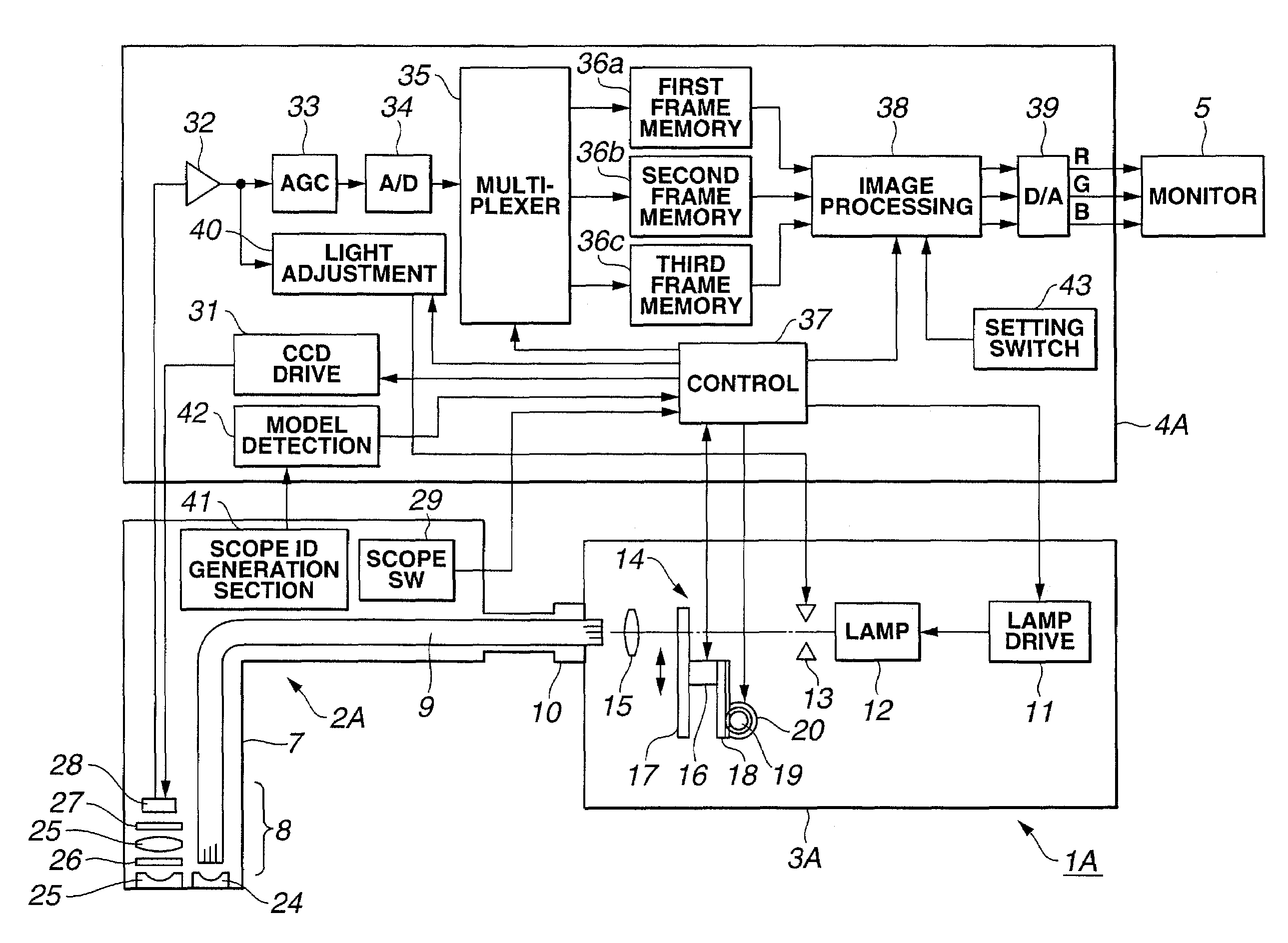
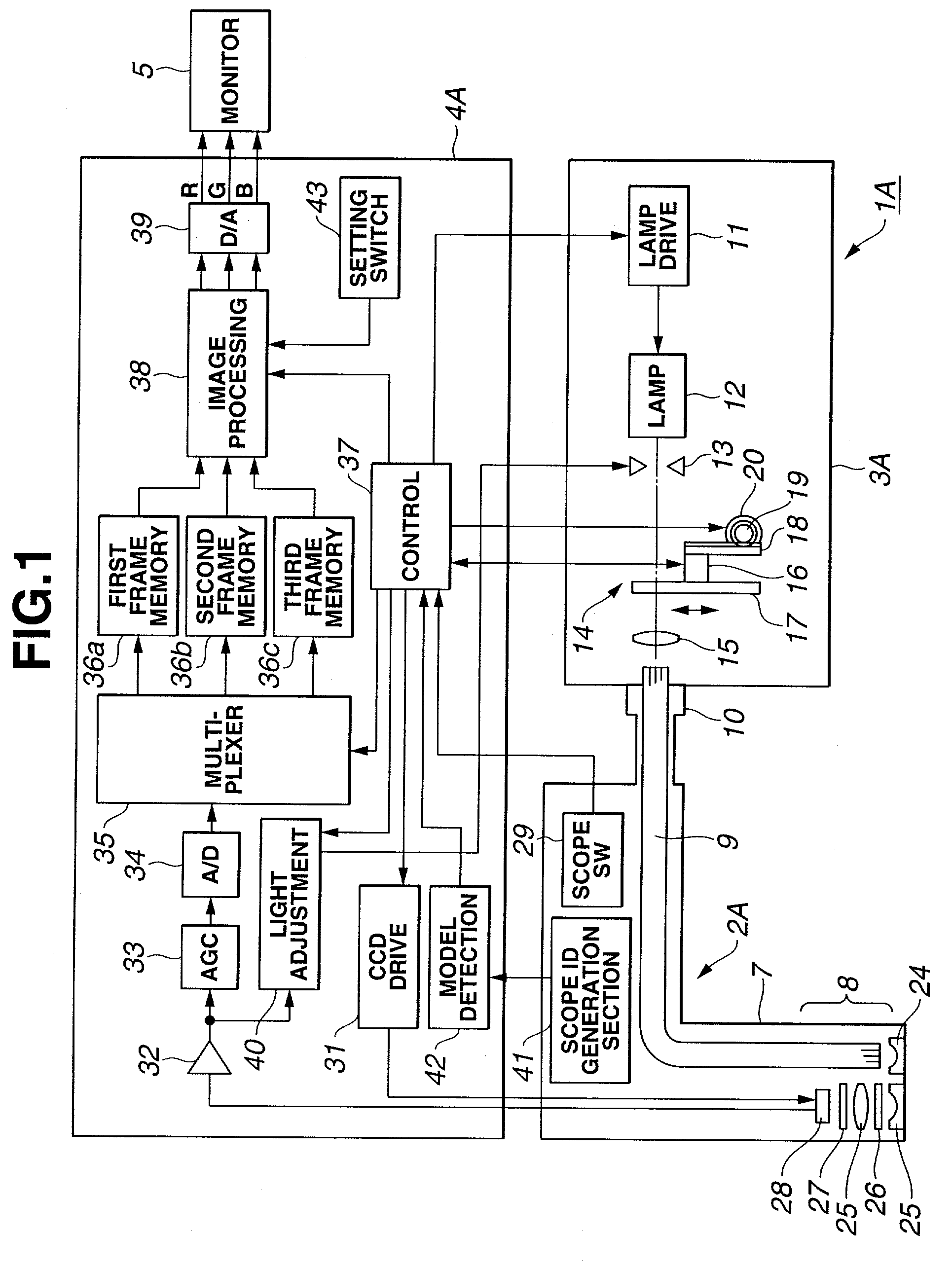
[0064]The endoscope system 1A, which has a normal-light observation mode and a fluorescent observation mode according to the first embodiment of the present invention shown in FIG. 1, comprises an electronic endoscope 2A which is inserted into a body cavity for observation, a light source unit 3A for emitting a light for normal-light observation and a light for excitation, a processor 4A for executing signal processing to create normal-light observation images and fluorescent images, and a monitor 5 for displaying images by normal light and images by fluorescence.

[0065]The electronic endoscope 2A has an elongated insertion section 7 which is inserted into a body cavity, and has illumination means and image capturing means which are enclosed in a tip 8 of the insertion section 7.

[0066]In the insertion section 7, a light guide fiber 9, for transmitting (guiding) ...

second embodiment

(Second Embodiment)

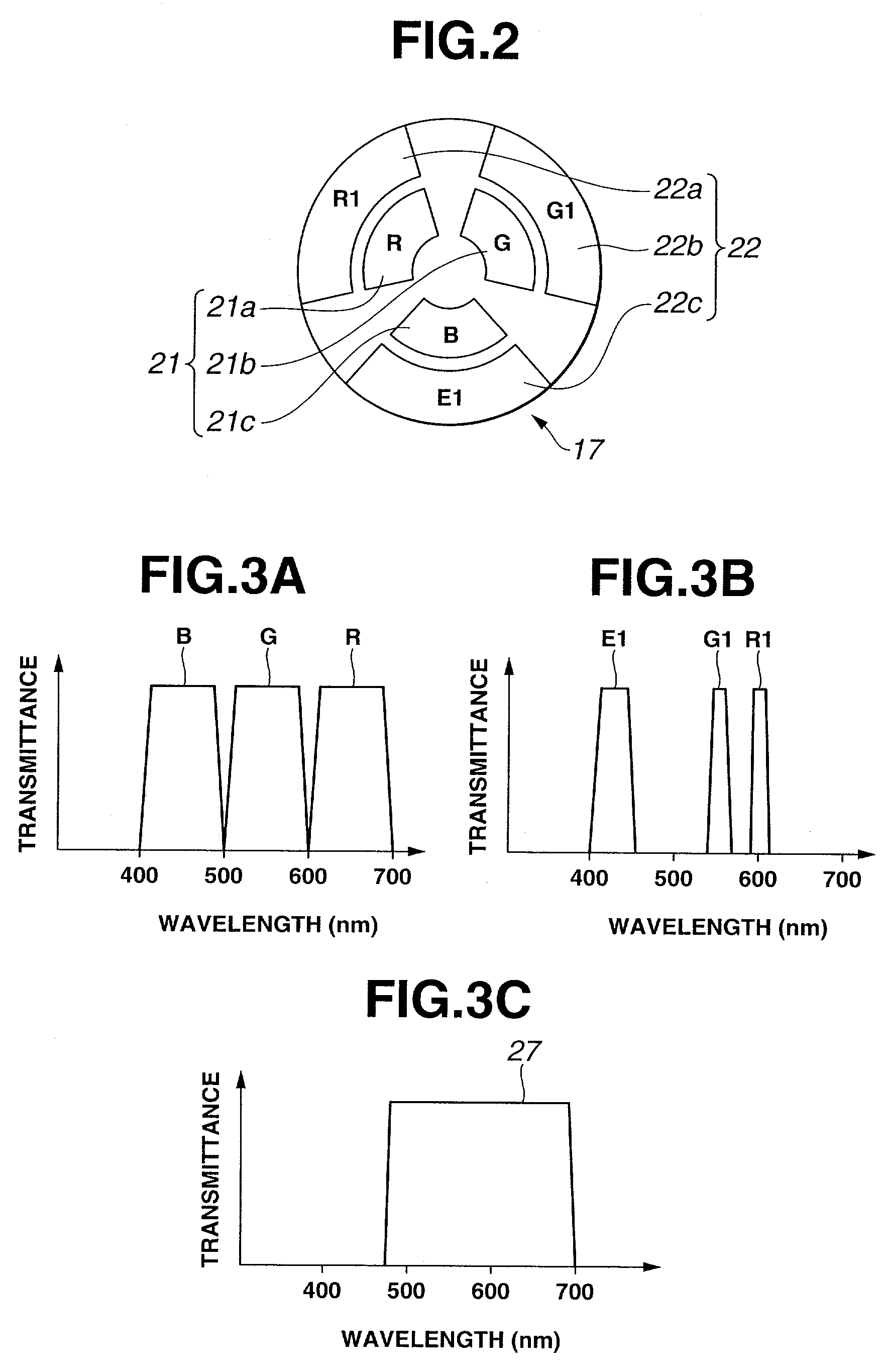
[0191]The second embodiment of the present invention will now be described with reference to FIG. 16. The configuration of the present embodiment is the same as the first embodiment, wherein a part of the characteristics of the excitation light cut filter 27, shown in FIG. 3C, has been changed.

[0192]FIG. 16 shows the characteristics of the intensity with respect to the wavelength of fluorescence obtained from a biological tissue which includes porphyrin. As FIG. 16 shows, when the biological tissue includes porphyrin, a wavelength band slightly longer than 620 nm may have a peak, which emits fluorescence due to porphyrin.

[0193]According to the present embodiment, to eliminate this influence of fluorescence generated by porphyrin, the longer wavelength side of the transmission characteristic of the excitation light cut filter 27 is cut at 620 nm, as indicated by the one-dotted line in FIG. 16, so that fluorescence at a wavelength longer than this wavelength is not ...

third embodiment

(Third Embodiment)

[0196]FIG. 17 shows the image processing circuit 38D of the third embodiment.

[0197]In this image processing circuit 38D, an enhancement conversion table 56, comparator 57, and ROM 58 are additionally installed to the configuration in FIG. 4.

[0198]According to the present embodiment, the enhancement conversion table 56 is installed between the input end Tc and the matrix circuit 45 in FIG. 4, and the signal EX of the fluorescent image is enhancement-processed by this enhancement conversion table 56, and is input to the matrix circuit 45.

[0199]The input ends Ta and Tb are connected to the matrix circuit 45, and are connected to the comparator 57, and by this comparator 57, it is detected whether the signals R1 and G1, to be input from the input ends Ta and Tb, deviate from a predetermined range, and the detection signal is input to the ROM 58 installed between the matrix circuit 45 and the range correction tables 46a to 46c.

[0200]The ROM 58 compares the luminance le...


PUM


Abstract

In the light source unit 3A, a switching filter section 14, which can switch the RGB filter for normal-light observation and a filter for fluorescent observation on the optical path, is installed in front of the lamp 12, where if the fluorescent image mode is selected, the excitation light in a part of the blue wavelength band is supplied to the electronic endoscope 2A, and the excitation light reflected by the subject side is shielded by the excitation light cut filter 27 in front of the CCD 28 so as to obtain the fluorescent image, and also the signal of the fluorescent image and the signals of the two reflected light images which are set in a predetermined wavelength band are passed through the image processing circuit 38, where a matrix circuit for appropriately allocating the color signals of the R, G and B channels is installed, and as a result, the images can be displayed on the monitor 5 in pseudo-colors in hues which allow easy identification of a normal tissue and a pathologically affected tissue.

Description

[0001]This application claims benefit of Japanese Application Nos. 2001-146755 filed on May 16, 2001, 2001-323936 filed on Oct. 22, 2001 and 2001-323937 filed on Oct. 22, 2001 the contents of which are incorporated by this reference.BACKGROUND OF THE INVENTION[0002]1. Field of the Invention[0003]The present invention relates to an endoscope system using normal light and fluorescence for obtaining normal reflected light images and fluorescent images.[0004]2. Description of the Related Art[0005]Endoscopes are widely used today in the medical field and the industrial field. Particularly in the medical field, a technology to obtain images which make it easier to identify normal tissue and abnormal tissue has been proposed, in addition to an endoscope system for obtaining normal-light images using conventional white light.[0006]For example, as a first prior art, Japanese Patent Laid-Open Publication No. 2001-137174 discloses a system for generating display signals mainly by reflecting th...

Claims


Application Information

Patent Timeline
IPC IPC(8): A61B1/06A61B6/00A61B1/04A61B1/045A61B5/00
CPCA61B1/00009A61B1/00059A61B1/00186A61B1/043A61B5/0084A61B1/0638A61B1/0646A61B1/0669A61B5/0071A61B1/045
Inventor UENO, HITOSHIOZAWA, TAKESHINAKAMURA, KAZUNARIHIRAO, ISAMIIBE, HIROSHIYOSHIMITSU, KOICHIMORIZANE, YUICHIKANEKO, MAMORUAKIMOTO, SHUNYATERAKUBO, MASAKIIMAIZUMI, KATSUICHIDOGUCHI, NOBUYUKITAKEHANA, SAKAEGONO, KAZUHIRO
Owner OLYMPUS CORP
Why Eureka
Try Eureka