Duty adjustment circuit

a duty adjustment circuit and duty adjustment technology, applied in pulse generators, pulse manipulation, pulse techniques, etc., can solve problems such as the possibility of erroneous operation or inoperable state, and the generation of clock signals with extremely short pulse widths, so as to suppress the adverse effects of high-level instantaneous noise

Inactive Publication Date: 2007-02-06
LAPIS SEMICON CO LTD
View PDF4 Cites 14 Cited by
  • Summary
  • Abstract
  • Description
  • Claims
  • Application Information

AI Technical Summary

Benefits of technology

[0007]One object of this invention is to provide a duty adjustment circuit which suppresses adverse effects of high-level instantaneous noise, and adjusts the duty ratio of a clock signal to a desired value (for example, 50%).
[0009]The input clock signal is frequency-divided by 2n, so that the influences of high-level instantaneous noise can be suppressed. Also, when the frequency is returned to the original frequency by the n stages of frequency doublers, delay times are adjusted such that the average voltage of the signal generated from each frequency doubler matches a reference voltage, so that a clock signal having a prescribed duty ratio can be generated.

Problems solved by technology

However, when noise of amplitude greater than the hysteresis (e.g., high-level instantaneous noise due to electrostatic discharge or other causes) is applied to the above described duty ratio correction circuit, this duty ratio correction circuit cannot exclude the noise, so that a clock signal with an extremely short pulse width is generated.
As a result, in a circuit which receives the clock signal, there is the possibility of erroneous operation or of entering an inoperable state.

Method used


Image

  • Duty adjustment circuit
  • Duty adjustment circuit
  • Duty adjustment circuit

Examples


embodiment 1

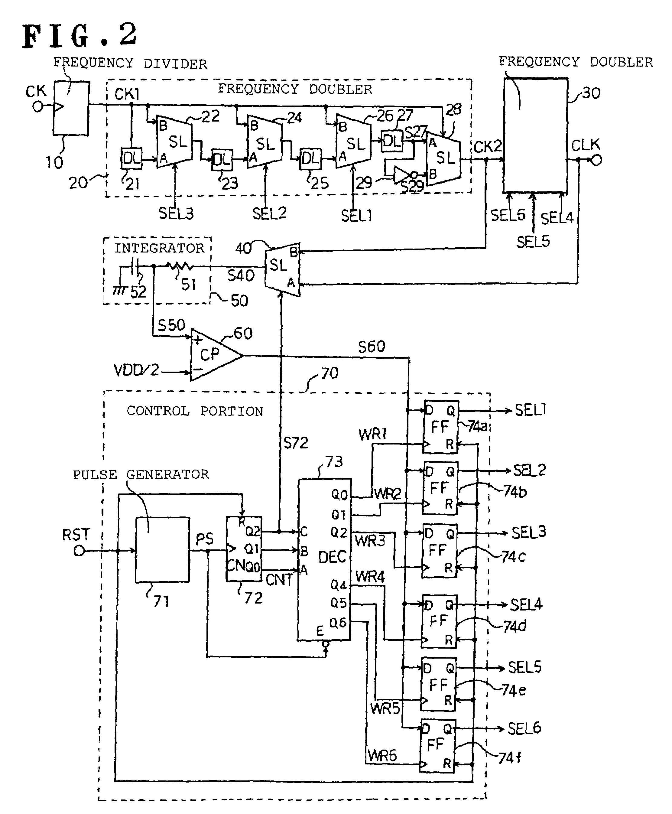
[0018]FIG. 2 is a circuit diagram of a duty adjustment circuit 5′, showing an embodiment of this invention.

[0019]This duty adjustment circuit 5′ has a frequency divider 10 which divides the frequency of the clock signal CK for adjustment by 4. This frequency divider 10 includes for example a two-bit binary counter, and outputs a clock signal CK1 with a duty ratio of 50%. The clock signal CK1 generated from the frequency divider 10 is provided to the frequency doubler 20.

[0020]The frequency doubler 20 is configured to generate a clock signal CK2 with double the frequency of the clock signal CK1, and also to enable adjustment of the duty ratio of the clock signal CK2 according to selection signals SEL1 to SEL3.

[0021]This frequency doubler 20 has a delay unit (DL) 21 to which the clock signal CK1 is introduced, and a selector (SL) 22. The output signal of the delay unit 21 is supplied to an input terminal A of the selector 22, and the clock signal CK1 is supplied to an input terminal B...


PUM


Abstract

In a duty adjustment circuit, a clock signal is frequency-divided to ½n by a frequency divider. In a first frequency doubler among n cascade-connected frequency doublers, the divided clock signal is delayed by a variable delay portion according to a control signal. The exclusive logical sum of the delayed signal and the divided clock signal in the frequency-doubling portion doubles the frequency. The average voltage of the frequency-doubled signal is detected by an average value detection portion, and is compared with a reference voltage by a comparison control portion. A control signal is fed back to the variable delay portion to cause the average voltage to become equal to the reference voltage. In this manner, a clock signal is generated from the last frequency doubler with frequency equal to that of the original clock signal, and with duty ratio adjusted to a desired value.

Description

BACKGROUND OF THE INVENTION[0001]1. Field of the Invention[0002]This invention relates to a duty adjustment circuit which adjusts the duty ratio of a clock signal to a desired value.[0003]2. Description of the Related Art[0004]Japanese Patent Kokai (Laid-open Application) No. 10-163823 discloses a conventional duty ratio correction circuit. In the following, the same reference numerals and symbols as used in Japanese Patent Kokai No. 10-163823 are used with parentheses for easier understanding of this prior art. This duty ratio correction circuit includes a first CR integration circuit (101) to integrate a clock signal (CKI) with a time constant (T1) shorter than a half-period thereof. The duty ratio correction circuit also includes a second CR integration circuit (102) to integrate the same clock signal (CKI) with another time constant (T2) substantially longer than the period thereof. The duty ratio correction circuit compares the output signals of the CR integration circuits (101...

Claims


Application Information

Patent Timeline
Patent Type & Authority Patents(United States)
IPC IPC(8): H03K7/08H03K5/04H03K3/017H03K5/00H03K5/156
CPCH03K5/00006H03K5/1565H03K2005/00156H03K2005/00058
Inventor NAGASUE, MAKOTO
Owner LAPIS SEMICON CO LTD
Why Eureka
Try Eureka