Back light unit for liquid crystal display device and method for manufacturing the unit

a technology of liquid crystal display device and back light unit, which is applied in the direction of optics, optical light guides, instruments, etc., can solve the problems of not being able to apply methods, increasing not only the cost of fixing but also the cost of production of back light unit, and causing remarkable cost-up, etc., to reduce the cost of fixing and product cost. , the effect of large siz

Inactive Publication Date: 2007-02-06
ROHM CO LTD
View PDF6 Cites 6 Cited by
  • Summary
  • Abstract
  • Description
  • Claims
  • Application Information

AI Technical Summary

Benefits of technology

[0012]That is, according to the invention, since various kind of sheets are fixed to the light guide plate surely and strongly without using metal fixing member as the related art, the invention does not cause large size and heavy weight and has advantages reducing drastically not only the cost for the fixing but also product cost of the back light unit.
[0013]Further, by constructing the pin provided at the horn for ultra sonic welding in taper shape of thin nose, the taper pin can be drown easily from the state pushing into various kind of sheets and the light guide plate. Therefore, since drawing out various kind of sheets is avoided at drawing the taper pin, reliability of welding in the hollow hole and welding strength are further improved.
[0014]Even further, by press-fitting the pin at a part close to one side surface of the light guide plate at plural places along the one side surface, various kind of sheets are fixed surely with the state not shifting sideways to the light guide, and it is avoided to generate wrinkles at the various kind of sheets because of difference of thermal expansion with the light guide plate.

Problems solved by technology

The former method using adhesive double-coated tape or stickness adhesive incurs remarkable cost-up because of manual work, and in the later method welding, welding area is small when each sheet is made of synthetic resin material different in kind of the light guide plate, thereby the method can not be applied because of low welding strength.
However, the method by the related art makes not only the cost for fixing but also cost for the production of the back light unit increase considerably because the metal sticking member such as eyelet is provided particularly and the metal sticking member is driven into the light guide plate.
Further, there is a problem that thickness of the back light unit increases, the size becomes large, and the weight remarkably increase because a head portion of the driven sticking member projecting from the surface of the sheet.

Method used


Image

  • Back light unit for liquid crystal display device and method for manufacturing the unit
  • Back light unit for liquid crystal display device and method for manufacturing the unit
  • Back light unit for liquid crystal display device and method for manufacturing the unit

Examples


Embodiment Construction

[0034]A mode for carrying out the invention will be described referring FIG. 1 to FIG. 5.

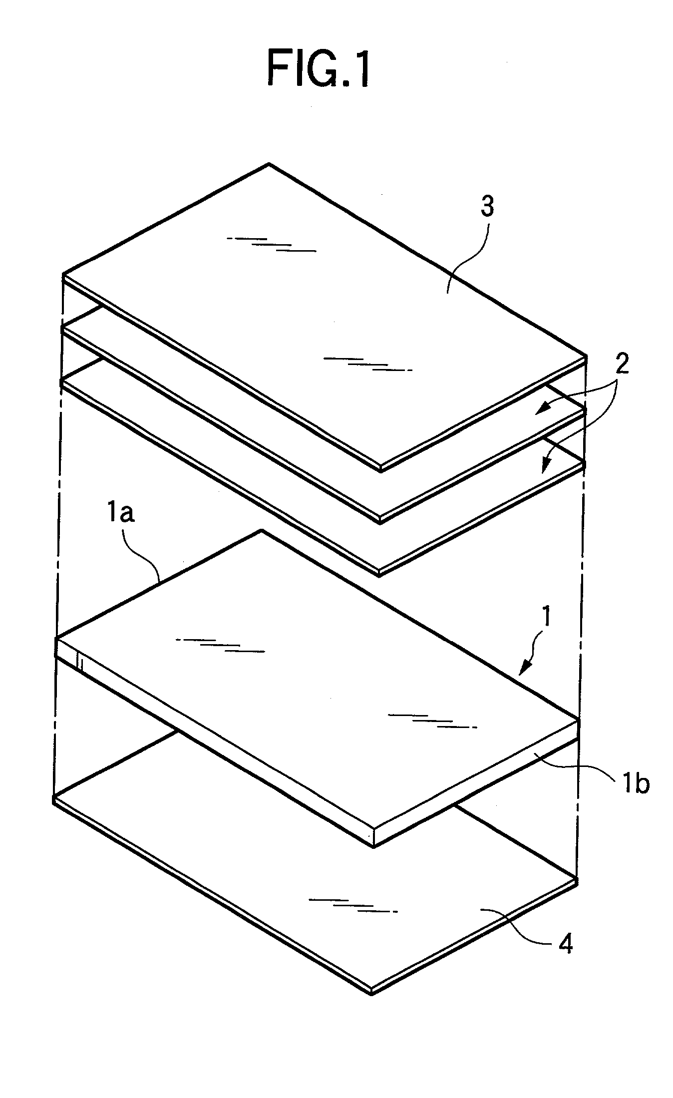
[0035]In FIG. 1, symbol 1 shows a light guide plate made of transparent synthetic resin such as acryl, symbol 2 shows a light diffusion sheet laminated surface side of the synthetic resin 1, and symbol 3 shows a brightness rising sheet laminated on the light diffusion sheet 2 in layers.

[0036]Symbol 4 shows a reflective sheet laminated at rear surface side of the light guide plate 1.

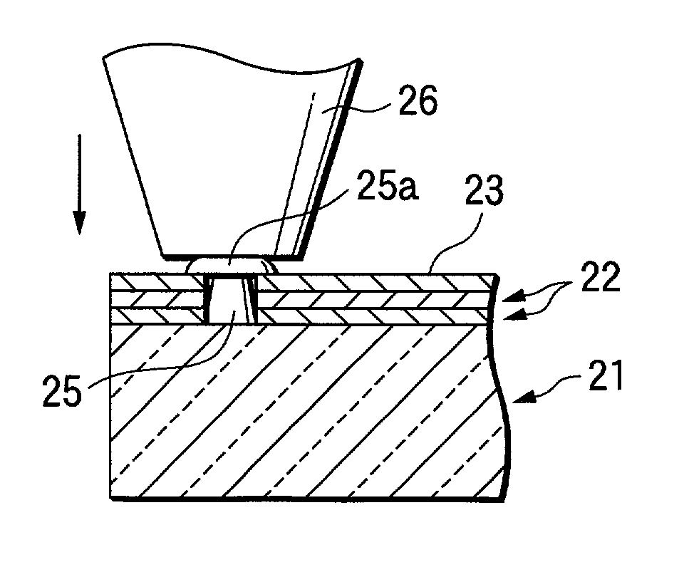
[0037]After laminating two light diffusion sheets 2 and one brightness rising sheet 3 on surface side of the light guide plate 1 in layers, these sheets 2 and 3 are fixed to the light guide plate using welding by ultrasonic vibration. For the fixing, the following method is adopted.

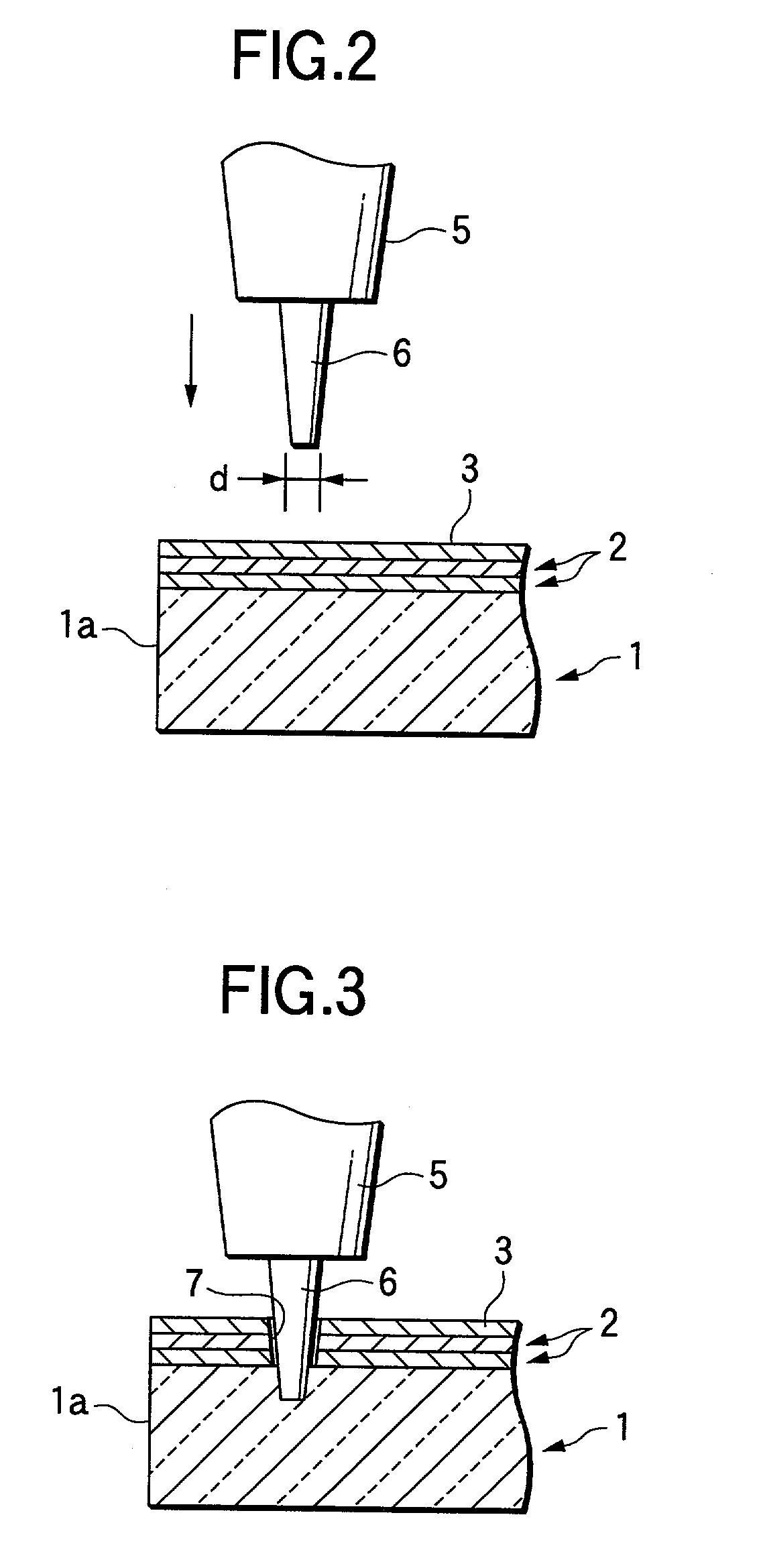
[0038]That is, a pin 6 of about 0.5 to 1 mm in diameter D at a horn for ultrasonic welding, and the pin 6 is press-fitted to the various kind of sheets 2 and 3 as shown in FIG. 2. By the press-fitting, the pin 8 is pushed into the depth rea...


PUM

PropertyMeasurementUnit
diameteraaaaaaaaaa
transparentaaaaaaaaaa
radiusaaaaaaaaaa

Abstract

A pin 6 provided at a horn 5 for ultrasonic welding is press-fitted to the depth reaching the light guide plate 1 breaking through the various kind of sheets 2 and 3 from surface side thereof.
Another embodiment of the invention is that pins 25 constructed so as to break through various kind of sheets 22 and 23 on the surface of the plate are provided on the light guide plate 21, and the various kind of sheets 22 and 23 are fixed on the light guide plate 1 by distorting by caulking using ultrasonic vibration of the tip end of the pin.

Description

BACKGROUND OF THE INVENTION[0001]1. Field of the Invention[0002]The present invention relates to a structure of a back light unit arranged at rear surface of a back light type liquid crystal display device and a method for manufacturing the unit.[0003]2. Description of the Related Art[0004]Generally, a back light type liquid crystal display device is constructed so that a light guide plate made of transparent synthetic resin such as acryl is provided at rear side thereof and light from a light source arranged at one end surface or both end surfaces of the light guide plate is scattered to whole liquid crystal display device through the light guide plate. A reflective sheet is laminated at a rear surface opposite to the liquid crystal display device among the light guide plate, on the other hand, at a surface of the liquid crystal display device among the light guide plate, a brightness rising sheet is laminated at least one light diffusion sheet made of synthetic resin, or the light...

Claims


Application Information

Patent Timeline
Patent Type & Authority Patents(United States)
IPC IPC(8): G02F1/1333G02F1/1335F21V8/00
CPCG02B6/0088G02B6/0065
Inventor KITAMURA, TAKESHIKONDO, YASUKAZU
Owner ROHM CO LTD
Why Eureka
Try Eureka