System for regulating optical output power

a technology of optical output power and control system, applied in the field of optical communication, can solve the problems of cost and speed requirements that require direct control of laser diode current, the cost, package size, and power consumption required by temperature stabilization preclude its use, and the long-term average optical power monitoring may no longer be suitable for regulating bias current. , the effect of power consumption

Inactive Publication Date: 2007-02-06
NETWORK APPLIANCE INC
View PDF5 Cites 36 Cited by
  • Summary
  • Abstract
  • Description
  • Claims
  • Application Information

AI Technical Summary

Problems solved by technology

However, cost and speed requirements call for direct control of the laser diode current.
However, in many applications the cost, package size, and power consumption required by temperature stabilization preclude its use.
During burst-mode operation, when the laser may be deliberately turned off for long intervals, long-term average optical power monitoring may no longer be suitable for regulating the bias current.

Method used


Image

  • System for regulating optical output power
  • System for regulating optical output power
  • System for regulating optical output power

Examples


Embodiment Construction

[0038]In general, the invention provides a circuit for regulating the average optical output power during a burst from a semiconductor laser, in which a data-modulated envelope is turned on and off in an asynchronous manner during burst-mode operation.

[0039]The inventive burst-mode APC system uses an externally available signal that follows the timing of the burst-mode data envelope as a gating signal. This gating signal quickly turns the laser driver chip completely ON or OFF, and maintains the previous feedback signal during OFF intervals when the optical monitor no longer provides an output.

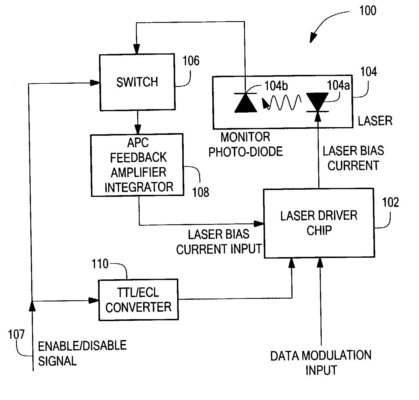
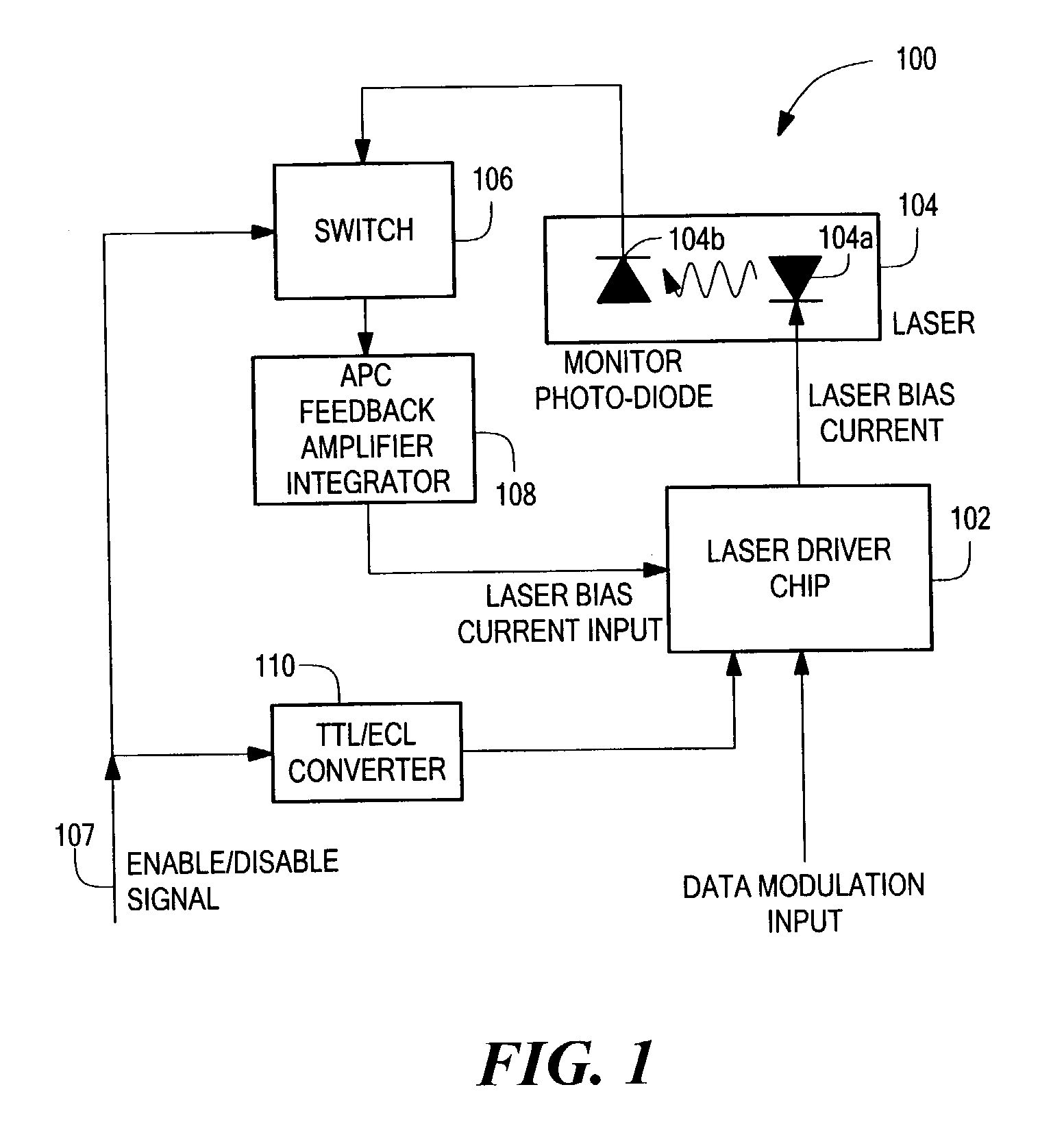
[0040]FIG. 1 shows a system 100 having burst-mode APC functionality in accordance with the present invention. A laser / driver chip 102 provides a laser bias current to a laser chip 104 having a laser diode 104a and a photodiode 104b for monitoring optical power. The photodiode 104b provides a signal to a switch 106 that receives an enable / disable signal and provides an output to an APC / feedback...


PUM


Abstract

Systems and methods for regulating optical power are described. A system for regulating optical power includes a laser driver circuit that receives an enable / disable signal and a data modulator input. The enable / disable signal regulates asynchronous mode operation. The system also includes a laser module including a laser diode emitter and a photodiode detector. The laser module is coupled to the laser driver circuit and receives a laser bias current from the laser driver circuit. The system also includes a switch coupled to the photodiode to receive a signal from the photodiode detector. The system also includes an automatic power control (APC) feedback circuit that receives a signal from the switch and provides a laser bias current feedback signal to the laser driver circuit to compensate for power output changes in the laser diode emitter over time.

Description

CROSS REFERENCE TO RELATED APPLICATIONS[0001]This application claims the benefit of U.S. Provisional Patent Application No. 60 / 351,065, filed on Jan. 23, 2002, which is incorporated herein by reference.STATEMENT REGARDING FEDERALLY SPONSORED RESEARCH[0002]Not Applicable.FIELD OF THE INVENTION[0003]The present invention relates to optical communication and, more particularly, to optical output power control.BACKGROUND OF THE INVENTION[0004]Certain acronyms may be used herein and are defined below:APC—Automatic Power ControlCMOS—Complementary metal-oxide-semiconductorcw—Continuous waveDFB—Distributed FeedbackECL—Emitter-coupled logicFET—Field-effect transistorGb / s, Gbps—Gigabits per second (data rate)Gigabit—109 bitsGHz—Giga Hertz, 109 cycles per second (frequency)LD—Laser diodeMQW—Multi-quantum wellMHz—Mega Hertz, 106 cycles per secondNIC—Network interface cardnm—Nanometer, 10−9 MetersPCB—Printed circuit boardPRBS—Pseudo-random bit sequences—Complex frequency, jω+αSPDT—Single-pole, d...

Claims


Application Information

Patent Timeline
Patent Type & Authority Patents(United States)
IPC IPC(8): H04B10/00H04B10/04H04B10/06H04B10/08H04B10/12
CPCH04B10/564
Inventor CHINN, STEPHEN R.LEE, PHILIP A.ROBERGE, JAMES K.
Owner NETWORK APPLIANCE INC
Why Eureka
Try Eureka