Saw blade having increased tooth stiffness and resistance to fatigue failure

a technology of fatigue failure and tooth stiffness, which is applied in the field of saw blades, can solve the problems of excessive vibration and noise, premature band breakage and/or other fatigue-related problems, and the blade life is limited, so as to prevent the collapse of the set and subsequent excessive heat generation, increase the cross-sectional width, and increase the tooth stiffness

Inactive Publication Date: 2007-02-13
IRWIN IND TOOL CO
View PDF33 Cites 63 Cited by
  • Summary
  • Abstract
  • Description
  • Claims
  • Application Information

AI Technical Summary

Benefits of technology

[0014]One advantage of the saw blades of the present invention is that the gullet radius R2 at the base of the rake face is greater than the depth D of the gullet. As a result, the saw blades of the present invention define an increased cross-sectional width at the set-bend plane of the tooth, and thus provide significantly increased tooth stiffness and, in turn, prevent the set collapse and subsequent excessive heat generation encountered in prior art wood-cutting band saw blades.
[0015]Another advantage of the saw blades of the present invention is that both the gullet radius R2 at the base of the rake face and the depth D of gullet are greater than the gullet radius R1 at the lower base of the clearance surfaces. Further, the ratio of R2 / R1 is greater than or equal to about 1.4. As a result, the band saw blades of the present invention relocate the point of critical crack initiation to a region of reduced stress as compared to prior art wood-cutting band saw blades, thus further increasing the resistance of the teeth to fatigue failure.
[0016]Accordingly, the saw blades of the present invention, and particularly the wood-cutting band saw blades of the present invention, have a tooth form and pitch pattern that prevent band breakage due to fatigue related issues, including increased cutting forces and heat due to set collapse and the subsequent reduction in overall kerf.

Problems solved by technology

One of the drawbacks associated with such prior art wood-cutting band saw blades is that blade life is limited due to fatigue related failures caused in part by the primary stress riser (R2) being located at the base of the rake face.
As a result, this type of tooth configuration, particularly when subjected to relatively high-cycle wood-cutting applications, can be subject to premature band breakage and / or other fatigue-related problems.
Also, by traditionally maintaining a uniform pitch distance P, the resulting forcing frequency creates excessive vibration and noise that prevents consistent loading of the teeth.
This random pattern of tooth loading results in a rough sawn surface that has difficulty maintaining a consistent cutting plane through regions of varying wood density, such as knots.

Method used


Image

  • Saw blade having increased tooth stiffness and resistance to fatigue failure
  • Saw blade having increased tooth stiffness and resistance to fatigue failure
  • Saw blade having increased tooth stiffness and resistance to fatigue failure

Examples


Embodiment Construction

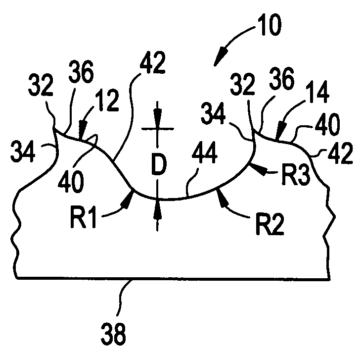
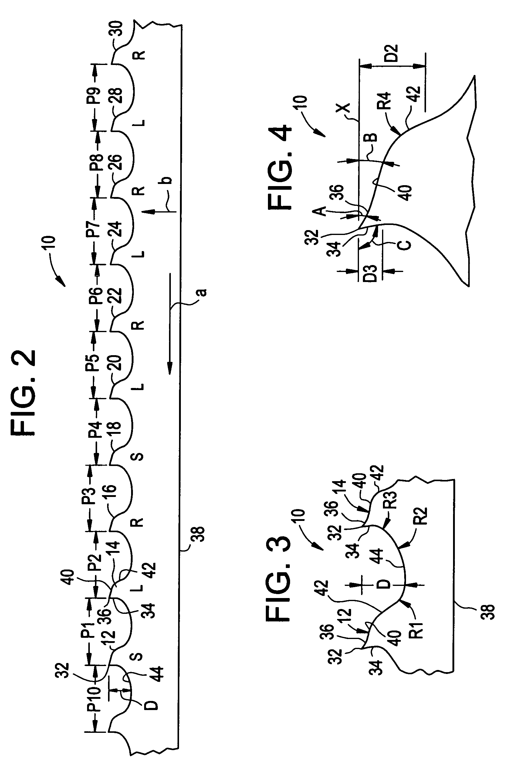
[0025]FIGS. 2 through 4, a wood-cutting band saw blade embodying the present invention is indicated generally by the reference numeral 10. The band saw blade 10 defines a cutting direction indicated by the arrow “a”, and a feed direction indicated by the arrow “b”. The band saw blade 10 comprises a plurality of recurrent or repetitive patterns of teeth defining a 10-tooth pitch pattern. Each pitch pattern is defined by a recurrent group of 10 successive teeth indicated by the reference numerals 12, 14, 16, 18, 20, 22, 24, 26, 28 and 30. As shown in FIG. 2, each tooth defines a respective pitch or tooth spacing P1 through P10. In the preferred embodiments of the present invention, and as indicated in FIG. 2, the pitch or tooth spacing is measured between the tips of adjacent teeth. However, as may be recognized by those of ordinary skill in the pertinent art based on the teachings herein, the pitch or tooth spacing may be measured between any of numerous other corresponding points be...


PUM

PropertyMeasurementUnit
radiusaaaaaaaaaa
relief angleaaaaaaaaaa

Abstract

A band saw blade comprising a plurality of teeth, wherein each tooth comprises a tip; a rake face formed on one side of the tip; a primary clearance surface formed on an opposite side of the tip relative to the rake face; a secondary clearance surface formed on an opposite side of the primary clearance surface relative to the tip; and a gullet located on an opposite side of the rake face relative to the tip and defining a depth (D) between a base surface of the gullet and the tip. Each tooth further defines a first gullet radius (R1) located between the gullet and the secondary clearance surface; a second gullet radius (R2) extending between a base surface of the gullet and the rake face; and a pitch (P) between the respective tooth and a preceding tooth. In each tooth, R2>D>RQ, and D / P is between about 25% and 35%.

Description

CROSS-REFERENCE TO RELATED APPLICATION [0001]This application claims priority on U.S. Provisional Application Ser. No. 60 / 612,604, filed Sep. 22, 2004, titled “Wood Cutting Saw Blade”, which is hereby incorporated by reference in its entirety.FIELD OF THE INVENTION [0002]The present invention relates to saw blades, and more particularly, to wood cutting saw blades, such as band saw blades.BACKGROUND INFORMATION [0003]Wood-cutting saw blades, and particular wood-cutting band saw blades, serve a critical function in performing semi-finish re-sawing of wood work pieces, such as wood cants, into boards in the fencing, pallet and other industries. A typical prior art wood-cutting band saw blade is illustrated in FIG. 1. Each tooth of the saw blade of FIG. 1 defines a gullet depth D, a pitch distance P between successive teeth, a first gullet radius R1 formed at the lower base of the clearance surface(s), a second gullet radius R2 formed at the base of the rake face, and a gullet transiti...

Claims


Application Information

Patent Timeline
Patent Type & Authority Patents(United States)
IPC IPC(8): B27B33/02B27B33/06
CPCB23D61/121Y10T83/9346Y10T83/935Y10T83/9319Y10T83/9317
Inventor CRANNA, MARK T.
Owner IRWIN IND TOOL CO
Why Eureka
Try Eureka