Orthopedic implant insertion instruments

a technology for orthopedic implants and insertion instruments, which is applied in the field of bone fracture treatment, can solve the problems of requiring patients to undergo surgery, affecting the accuracy of orthopedic implant insertion, so as to achieve accurate determination of the length of the orthopedic implan

Active Publication Date: 2007-02-13
SYNTHES USA
View PDF50 Cites 69 Cited by
  • Summary
  • Abstract
  • Description
  • Claims
  • Application Information

AI Technical Summary

Benefits of technology

[0018]The measurement device can be used generally during pre-operation to help surgeons determine the dimensions of the orthopedic implant needed to address a fracture or impending fracture that may be present in an affected bone. The measurement device can further help surgeons determine additional orthopedic measurements such as relative bone fragment angles and, in the case of bones like the femur, the angle of the femoral neck or the angle of equivalent bony structure. The orthopedic implant measurement device has an elongated body with a set of scaled notches disposed partially along a side of the body for determining an implant length. The measurement device also has a set of scaled tabs disposed partially along a side of the body for determinin

Problems solved by technology

These fractures are typically debilitating and often require the patient to undergo surgery.
However, even when the treatment of the fracture does not call for a complicated procedure such as complete replacement, the proper setting of a fractured bone can still pose substantial challenges to even the most skilled orthopedic surgeon.
These difficulties include dealing with the shape and positioning of the bones or bone fragments when aligning the fracture and the accompanying complications regarding the proper placement of

Method used


Image

  • Orthopedic implant insertion instruments
  • Orthopedic implant insertion instruments
  • Orthopedic implant insertion instruments

Examples


Embodiment Construction

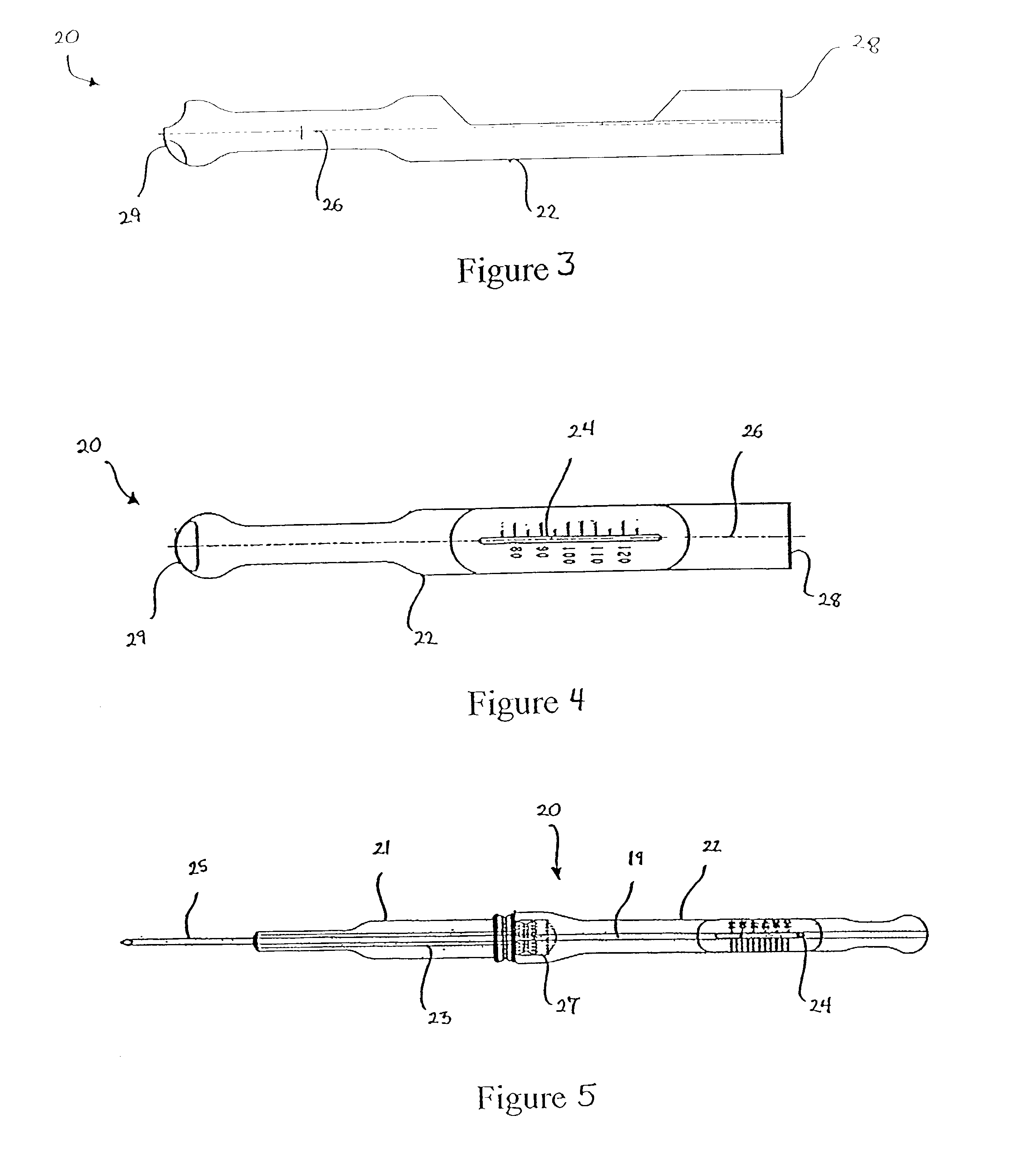
[0044]FIG. 1 shows an exemplary embodiment of a measuring device used with the orthopedic implant insertion instruments of the present invention. Measuring device 10 can be used generally during pre-operation or intra-operation to help surgeons determine the dimensions of the orthopedic implant needed to address a fracture or impending fracture that may be present in an affected bone. Measuring device 10 can further help surgeons determine additional orthopedic measurements such as relative bone fragment angles and, in the case of bones like the femur, the angle of the femoral neck or the angle of equivalent bony structure. Generally speaking, measuring device 10 comprises elongated body 12, which is made of a radiopaque material. In a preferred embodiment, located along a partial length of body 12 are a series of spaced notches 14 with corresponding numerical designations that assist surgeons in determining the length of an implant needed to address a bone fracture. In an exemplary...


PUM


Abstract

Orthopedic implant insertion instruments for precision guiding of a fracture fixation implant into fractured bone to promote healing are disclosed. The implant insertion instruments comprise an insertion handle for implantation of a first fixation implant, an aiming arm for precise guiding of a second fixation implant into bone, a guide sleeve for protection of soft tissue and for translational and rotational control of the second fixation implant, and a drive shaft with coupling screw for attachment to the second fixation implant and for driving the second fixation element through the aiming arm and guide sleeve into the fractured bone. The implant insertion instruments also include a soft tissue clearance device to aid the surgeon in inserting the first fixation implant into the fractured bone. Also disclosed is a measuring device that reduces measuring errors made by a user and a measuring device that determines implant length, diameter, and angle of insertion.

Description

CROSS-REFERENCE TO RELATED APPLICATIONS[0001]The present application is related to U.S. patent application Ser. No. 09 / 978,002, entitled “Bone Fixation System” filed on Oct. 17, 2001, and claims priority to provisional patent application No. 60 / 329,536 filed on Oct. 17, 2001. The entire contents of both of these applications is expressly incorporated herein by reference thereto.FIELD OF THE INVENTION[0002]This invention relates in general to the treatment of bone fractures, and more particularly, to an orthopedic implant insertion system for improving guidance and placement of a fracture fixation implant into fractured bone to promote healing.BACKGROUND OF THE INVENTION[0003]Skeletal fractures are common injuries. These fractures are typically debilitating and often require the patient to undergo surgery. Depending on the severity of the fracture, the orthopedic surgeon has several options for treatment, ranging from simple fracture reducing implants to complete prosthetic replaceme...

Claims


Application Information

Patent Timeline
IPC IPC(8): A61B17/62A61B17/58A61B17/17A61B17/90A61B17/92A61B19/00A61F2/46
CPCA61B17/1725A61B2019/467A61B2019/461A61B17/921A61B2090/067A61B2090/061A61B17/58
Inventor ROTH, CHRISTOPH A.GELTZ, CHARLES E.WILSON, FRANK A.
Owner SYNTHES USA
Why Eureka
Try Eureka