Plasma detemplating and silanol capping of porous dielectric films

a dielectric film and silanol technology, applied in the field of porous film preparation, can solve the problems of significant challenges, however, associated with forming porous dielectric materials, and significantly increasing the overall dielectric constant of films

Inactive Publication Date: 2007-02-13
NOVELLUS SYSTEMS
View PDF80 Cites 128 Cited by
  • Summary
  • Abstract
  • Description
  • Claims
  • Application Information

AI Technical Summary

Benefits of technology

[0009]The present invention addresses these needs by providing improved methods of preparing a low-k dielectric material on a substrate. The methods involve providing a precursor layer comprising a hydrocarbon porogen in a dielectric matrix and exposing the precursor layer to a plasma having a silanol capping agent to remove the porogen to create voids within the dielectric matrix and concurrently protect the dielectric matrix with hydrophobic protecting groups. Porogen removal and silanol capping may be performed contemporaneously or sequentially. If performed sequentially, silanol capping is performed without first exposing the dielectric matrix to moisture or ambient conditions.

Problems solved by technology

There are significant challenges, however, associated with forming a porous dielectric material, particularly in the porogen removal process.
Unfortunately, since water has a dielectric constant of about 80, this significantly increases the overall dielectric constant for the film.

Method used


Image

  • Plasma detemplating and silanol capping of porous dielectric films
  • Plasma detemplating and silanol capping of porous dielectric films
  • Plasma detemplating and silanol capping of porous dielectric films

Examples


embodiment 1

Plasma Porogen Removal and In Situ Silanol Capping

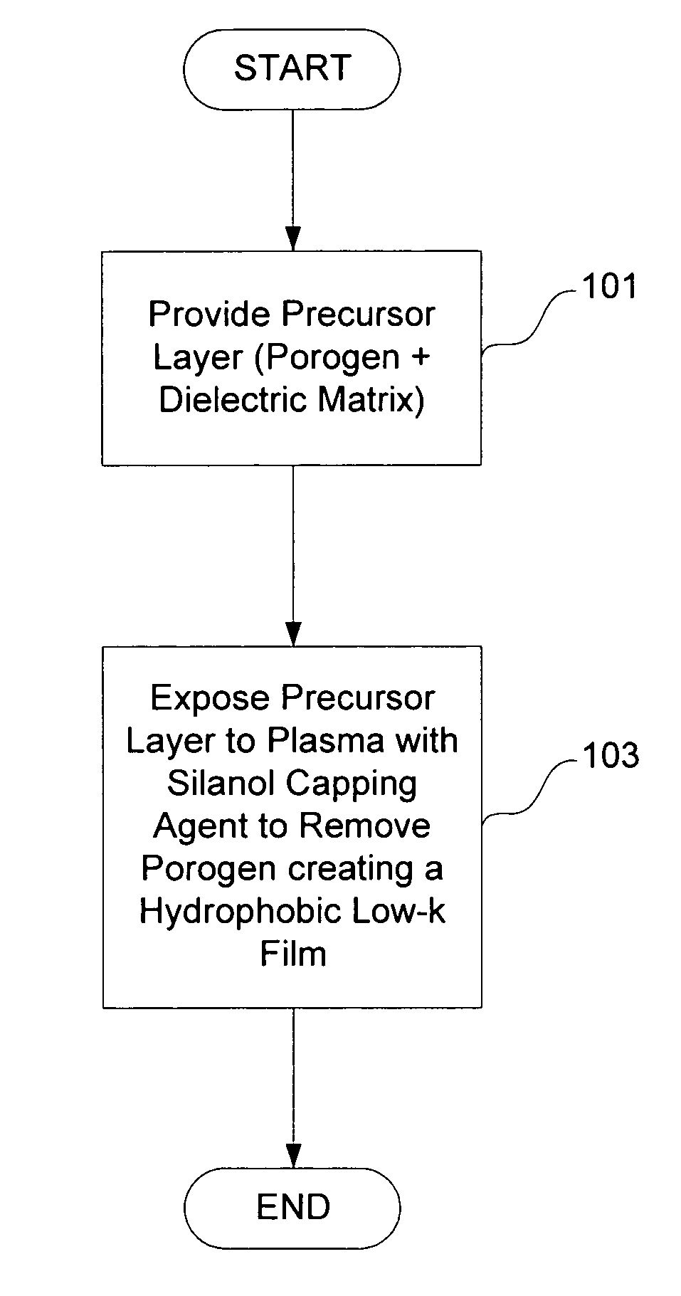
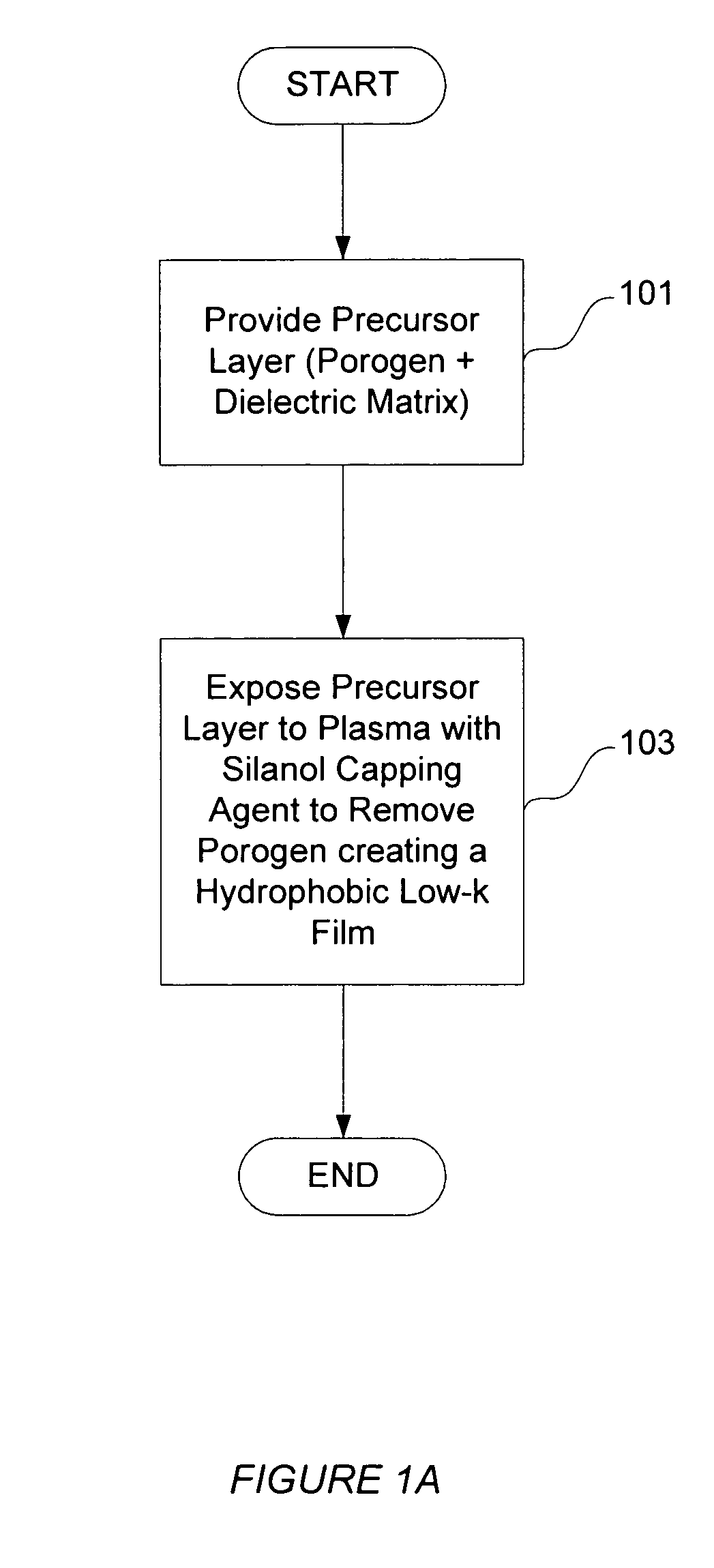
[0039]FIG. 1A is a flowchart summarizing aspects of a first embodiment of the invention. First, as indicated at block 101, a substrate with a deposited precursor layer is provided. As described previously, the precursor layer may be an ordered or mesoporous precursor layer or it may be a non-ordered precursor layer. In preferred embodiments, the precursor layer is an ordered mesoporous layer comprising template porogen and a silicon-containing dielectric phase which will become the dielectric matrix once the porogen is removed. In cases wherein a mesoporous precursor layer is used, this process is called “detemplating.”

[0040]Next, one of various suitable plasma techniques is used to 1) remove at least a portion of the porogen material from the precursor layer and to 2) protect or “cap” hydrophilic portions of the dielectric matrix using a “silanol capping” agent. See 103. For removing porogen, any suitable plasma method that can caus...

embodiment 2

Plasma Porogen Removal Followed by Silanol Capping

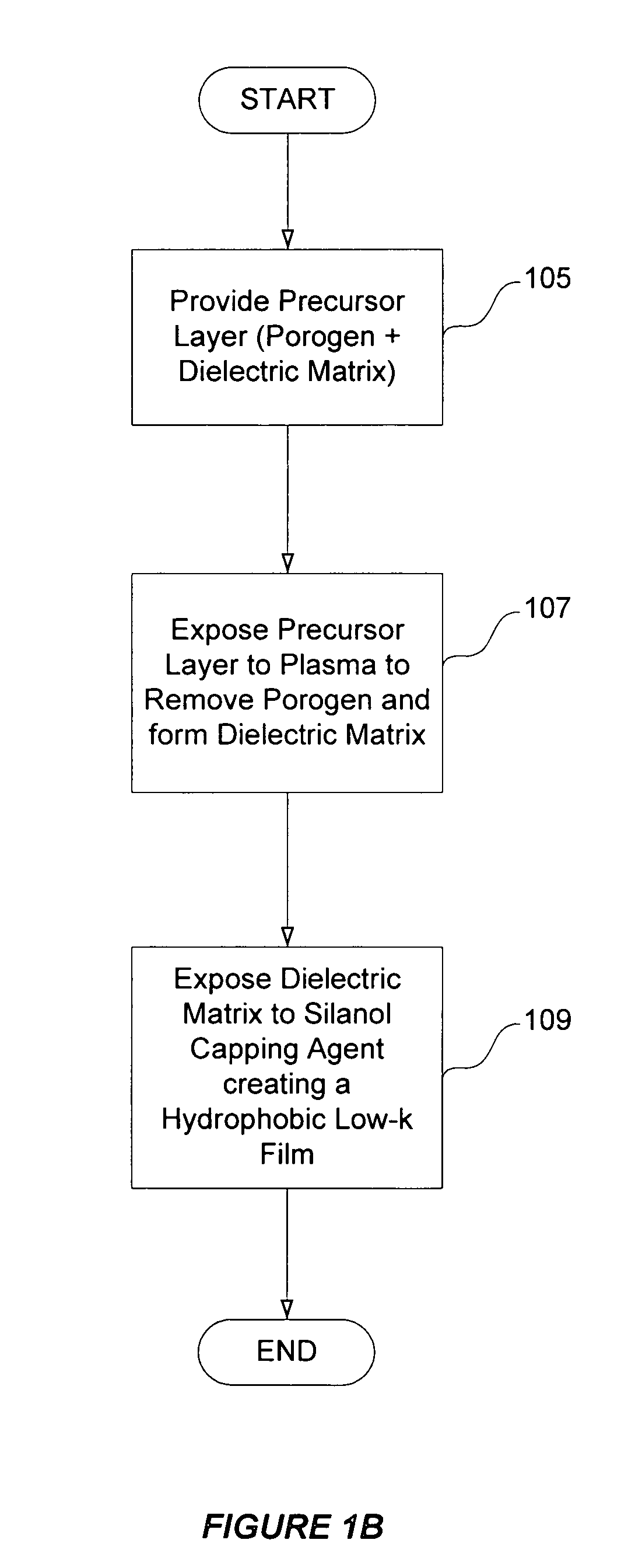
[0047]FIG. 1B is a flowchart summarizing aspects of a second embodiment of the invention. First, as indicated by block 105, a substrate with a deposited precursor layer is provided as described in the previous embodiment. Next, as indicated in block 107, the porogen is removed from the precursor layer using a plasma process. As in the previous embodiment, the plasma may be a reducing plasma or an oxidizing plasma. Plasma conditions and compositions are similar to those of the previous embodiment but without the silanol capping agent. As in the previous embodiment, the porogen decomposition components and other byproducts may be removed by volatilization (e.g., heating the wafer substrate and pumping away the residuals).

[0048]After porogen removal, the resulting dielectric matrix is exposed to a silanol capping agent, as indicated by process block 109. Note that this silanol capping process is preferably done without exposing the diel...


PUM

PropertyMeasurementUnit
poweraaaaaaaaaa
temperatureaaaaaaaaaa
chamber pressureaaaaaaaaaa

Abstract

Methods of preparing a low-k dielectric material on a substrate are provided. The methods involve using plasma techniques to remove porogen from a precursor layer comprising porogen and a dielectric matrix and to protect the dielectric matrix with a silanol capping agent, resulting in a low-k dielectric matrix. Porogen removal and silanol capping can occur concurrently or sequentially. If performed sequentially, silanol capping is performed without first exposing the dielectric matrix to moisture or ambient conditions.

Description

CROSS-REFERENCE TO RELATED APPLICATIONS[0001]This application is a continuation-in-part claiming priority under 35 USC 120 from U.S. patent application Ser. No. 10 / 404,693 filed Mar. 31, 2003 by Humayun, et al., and titled “METHOD FOR FORMING POROUS FILMS BY POROGEN REMOVAL COMBINED WITH IN SITU SURFACE MODIFICATION.” This application is incorporated herein by reference for all purposes. This application is also related to U.S. patent application Ser. No. 10 / 672,305, filed Sep. 26, 2003; U.S. patent application Ser. No. 10 / 672,311, filed Sep. 26, 2003; and U.S. patent application Ser. No. 10 / 807,680, filed Mar. 23, 2004.FIELD OF THE INVENTION[0002]This invention relates to methods for preparing porous films using porogen technology. More specifically, the methods involve providing a precursor film comprising porogen and a dielectric matrix and removing the porogen and protecting silanol groups within the dielectric matrix using plasma techniques. The resulting material can be used a...

Claims


Application Information

Patent Timeline
Patent Type & Authority Patents(United States)
IPC IPC(8): H01L21/31H01L21/469
CPCH01L21/02126H01L21/02203H01L21/31695H01L21/3105H01L21/0234
Inventor WANG, FENGSCHULBERG, MICHELLE T.SUN, JIANINGHUMAYUN, RAASHINAVAN CLEEMPUT, PATRICK A.
Owner NOVELLUS SYSTEMS
Why Eureka
Try Eureka