Low dielectric constant composite material containing nano magnetic particles, and optical and semiconductor devices using the low dielectric constant composite material

a low dielectric constant, composite material technology, applied in the direction of magnetic bodies, semiconductor/solid-state device details, instruments, etc., can solve the problems of inability to meet the requirements etc., to achieve the effect of low dielectric constan

Inactive Publication Date: 2005-02-01
POHANG UNIV OF SCI & TECH
View PDF14 Cites 4 Cited by
  • Summary
  • Abstract
  • Description
  • Claims
  • Application Information

AI Technical Summary

Benefits of technology

According to the present invention, the internal electric field, which is induced by externally applied electric field, can be disturbed, thereby providing a composite having an ultra low dielectric constant.

Problems solved by technology

In more detail, in order to improve the performance of a semiconductor device or a display device or to enhance the integration level thereof, there has been a trend of sharply decreasing circuit interconnect line widths, which may increasingly bring about unacceptable interconnect resistance-capacitance (RC) delays.
It is recognized that the RC delays reduce the operation speed of a semiconductor device, thus adversely affecting faster operation of the semiconductor device.
However, since poly(benzoxazole) has a poor photoactive property, it cannot be readily to be used as an interlayer dielectric (ILD) or an intermetal dielectric (IMD).
However, in this case the dielectric constant is undesirably increased to 2.8.
Nevertheless, in order to reduce the dielectric constant, which is still high due to the dielectric constant of diamond, that is, approximately 5.7, there has been an attempt to add hydrogen and fluorine, resulting in serious degradation of thermal stability.
However, porous dielectrics based on the methods disclosed in the referenced patents have poor mechanical properties, a high hygroscopicity due to a high surface energy and a low dielectric strength.

Method used


Image

  • Low dielectric constant composite material containing nano magnetic particles, and optical and semiconductor devices using the low dielectric constant composite material
  • Low dielectric constant composite material containing nano magnetic particles, and optical and semiconductor devices using the low dielectric constant composite material
  • Low dielectric constant composite material containing nano magnetic particles, and optical and semiconductor devices using the low dielectric constant composite material

Examples


embodiment 1

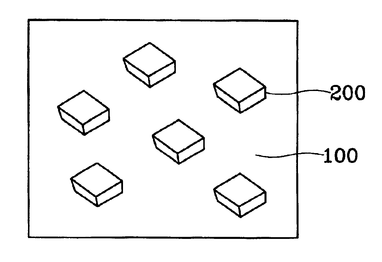
FIG. 1 is a schematic cross-sectional view for explaining a composite containing nano magnetic particles according to the present of the present invention.

In detail, a composite according to a first embodiment of the present invention includes a dielectric matrix 100 and nano magnetic particles 200 distributed in the dielectric matrix 100. The nano magnetic particles 200 may be of a spherical or non-spherical shape. Specifically, the non-spherical shape, e.g., ellipsoids, needle, plate or tetrahedral, is preferred. Otherwise, spherical nano magnetic particles may be mixed with non-spherical nano magnetic particles 200.

The dielectric matrix 100 is formed of an inorganic material such as silica, alumina or hydrosilsesquioxane, or an organic material such as polyimide, epoxy, polymethylmethacrylate (PMMA) or methyl silsesquioxane.

The nano magnetic particles 200 may be formed of a superparamagnetic material including a transition metal such as cobalt (Co) or nickel (Ni) or an oxide such...

example 1

Step 1. Synthesis of Surfactant (Salt) Having Metal Counter Ion

Nano magnetic particles were prepared by chemical sedimentation. 500 ml of 1M aqueous solution of iron (II) chloride was placed into 250 ml of 0.1M aqueous solution of sodium dodecylsulfate (C12H25NaO4S), which is an anion surfactant, and then reacted under a nitrogen atmosphere for 12 hours. When an orange color suspension was formed, a salt was separated from the resultant by sedimentation at 2° C. The separated salt was subjected to water-washing with a 0.1 M aqueous solution of iron (II) chloride three to five times and then recrystallized in water held at 50° C., to obtain high-purity iron (II) dodecylsulfate salt (Fe(DS)2). Similarly, instead of iron (II) chloride, nickel (II) chloride and zinc (II) chloride were used in the reaction to obtain a nickel (II) dodecylsulfate salt (Ni(DS)2) and zinc (II) dodecylsulfate salt (Zn(DS)2), respectively. The critical micelle concentrations of these salts are shown in Table 1...

example 2

Synthesis of Nano Magnetic Particle / Polyimide (PI) Composite

The nano magnetic particles prepared in steps 2 and 3 of Example 1 were unformly dispersed in a PI matrix to form a nano composite. The PI used as the matrix was prepared in the following manner and its physical properties were then measured.

To 115.97 g of anhydrous n-methyl-pyrrolidone (NMP) were added 6.37 g (0.029 mol) of 1,2,4,5-benzenetetracarboxylic acid (pyromellitic dianhydride (PDMA)), 11.50 g (0.036 mol) of 3,3′,4,4′-benzophenone tetracarboxylic dianhydride (BTDA), 13.00 g (0.065 mol) of 4,4′-diaminodiphenylether (ODA), and mixed at 10° C. under a nitrogen atmosphere for 6 hours, to polymerize polyamic acid having 20% solid content. The reactants used are ones that are commercially available. NMP was added to the polyamic acid having 20% solid content to prepare polyamic acids having 2%, 5% and 10% solid contents, respectively.

After polymerization, the higher viscosity of the polyamic acid was reduced to 20000 to ...


PUM

PropertyMeasurementUnit
glass transition temperatureaaaaaaaaaa
dielectric constantaaaaaaaaaa

Abstract

A composite containing nano magnetic particles is provided. The composite includes nano magnetic particles in a dielectric matrix. The matrix is made of an inorganic material such as silica, alumina, or hydrosilsesquioxane, or an organic material such as polyimide, polymethyl methacrylate, or methyl silsesquioxane. The nano magnetic particles consist of Fe2O3, chromium oxide, europium oxide, NiZn-ferrite, MnZn-ferrite, yttrium-iron garnet, or indium In.

Description

BACKGROUND OF THE INVENTION1. Field of the InventionThe present invention relates to a composite employed to a semiconductor device or a display device, and more particularly, to a composite containing nano magnetic particles to exhibit such an electromagnetic characteristic as an ultra low dielectric constant.2. Description of the Related ArtAs an electromagnetic device, for example, a semiconductor device or a display device, has become highly integrated, it is necessary to employ a dielectric material having a relatively lower dielectric constant in such a device.In more detail, in order to improve the performance of a semiconductor device or a display device or to enhance the integration level thereof, there has been a trend of sharply decreasing circuit interconnect line widths, which may increasingly bring about unacceptable interconnect resistance-capacitance (RC) delays. To solve this problem, it is required to reduce the dielectric constant of a dielectric material used as ...

Claims


Application Information

Patent Timeline
Patent Type & Authority Patents(United States)
IPC IPC(8): G02F1/00H01F1/00G02F1/29
CPCB82Y25/00G02F1/0009H01F1/0063G02F1/0036G02F1/29H01B3/00
Inventor PARK, CHAN EONKANG, JIN HO
Owner POHANG UNIV OF SCI & TECH
Why Eureka
Try Eureka