
Semiconductor device, temperature sensor, and electronic apparatus comprising it

a technology of electromagnetic conductor and temperature sensor, which is applied in the field can solve the problems of high accuracy and linearity, high accuracy and irregular voltage difference vf, and the configuration of integrated circuit-type temperature sensor b>a /b> often proves unsuitable for use in controlling or driving apparatus, etc., and achieves high linearity and accuracy. high

Inactive Publication Date: 2007-02-13
ROHM CO LTD
View PDF7 Cites 72 Cited by
  • Summary
  • Abstract
  • Description
  • Claims
  • Application Information

AI Technical Summary

Benefits of technology

The solution enables precise and linear detection of ambient temperature, reducing errors and ensuring stable performance across different supply voltages, making it suitable for demanding applications such as hard disk drive and DVD drive apparatuses.

Problems solved by technology

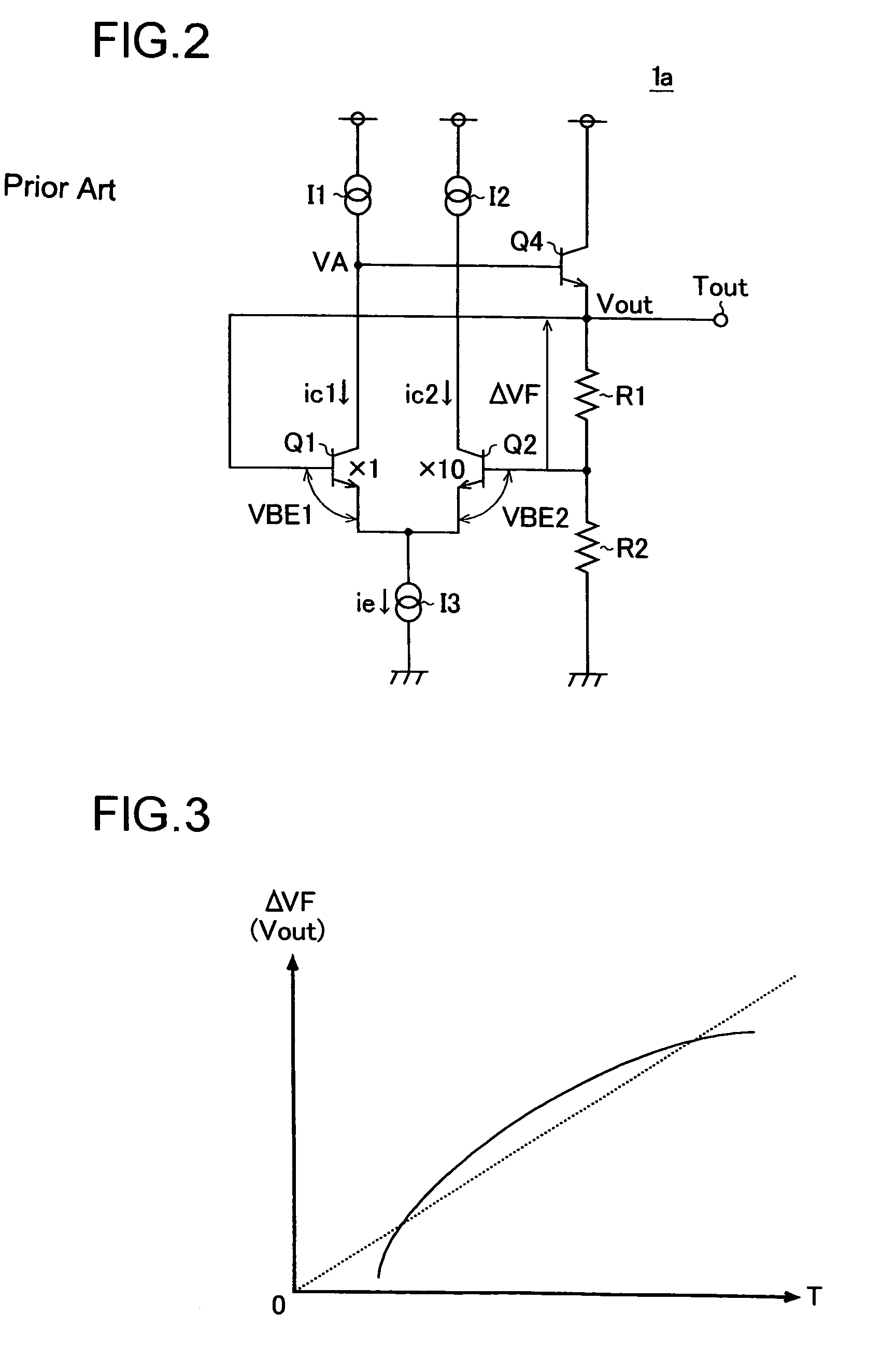
Thus, disadvantageously, as indicated by a solid line in FIG. 3, the voltage difference ΔVF deviates irregularly from the ideal straight line expressed by formula (3) above.
For this reason, the integrated-circuit-type temperature sensor 1a configured as described above often proves to be unsuitable as a temperature sensor for use in a controlling or driving apparatus for an electronic apparatus (for example, a hard disk drive apparatus or DVD drive apparatus incorporated in a car navigation system) that needs to detect the ambient temperature with high accuracy and high linearity.

Method used


Image

  • Semiconductor device, temperature sensor, and electronic apparatus comprising it
  • Semiconductor device, temperature sensor, and electronic apparatus comprising it
  • Semiconductor device, temperature sensor, and electronic apparatus comprising it

Examples


Embodiment Construction

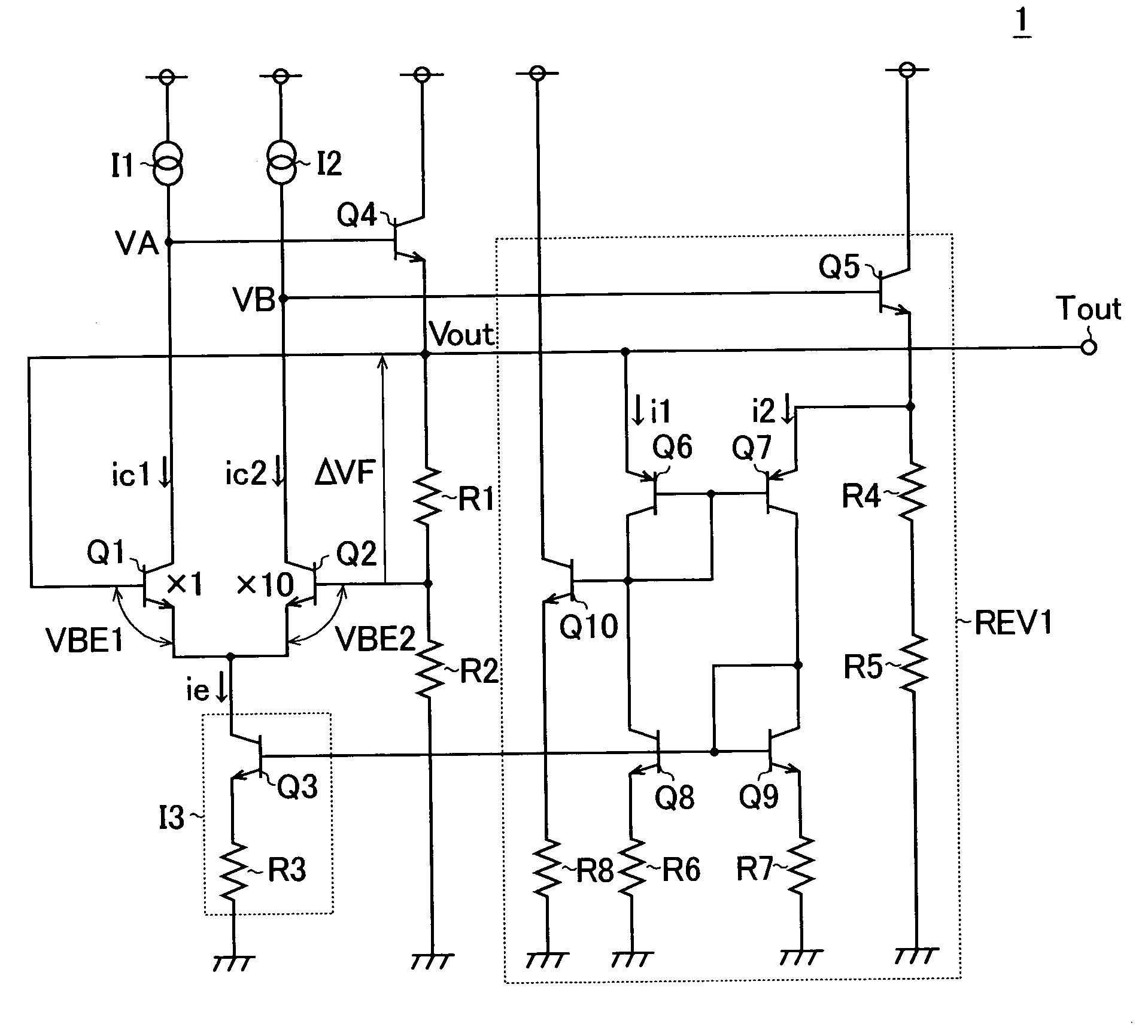
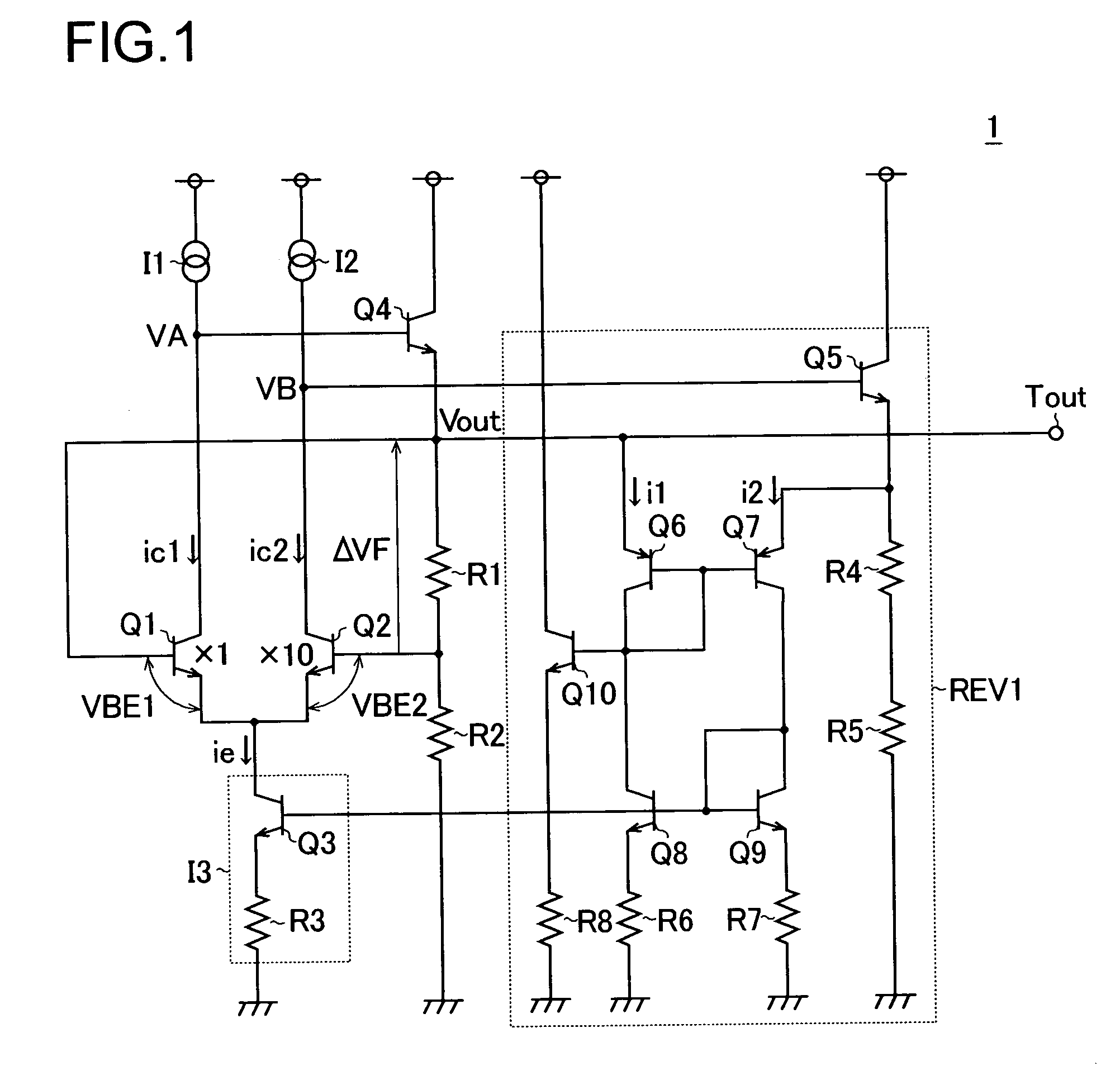
[0020]FIG. 1 is a circuit diagram showing an integrated-circuit-type temperature sensor embodying the invention. The integrated-circuit-type temperature sensor 1 of this embodiment includes, in addition to the conventional configuration shown in FIG. 2, a feedback circuit REV1 for controlling the collector voltages VA and VB of the transistors Q1 and Q2 and their emitter current ie such that the collector voltages VA and VB of the transistors Q1 and Q2 vary with similar temperature responses. Accordingly, such components as are found also in the conventional integrated-circuit-type temperature sensor 1a are identified with the same reference symbols as those used in FIG. 2, and their explanations will be omitted. In the following description, emphasis is placed on the characteristic features of this embodiment, namely the configuration and operation of the feedback circuit REV1.

[0021]As shown in FIG. 1, the feedback circuit REV1 of this embodiment includes: an npn-type transistor Q5...


PUM

PropertyMeasurementUnit
temperatureaaaaaaaaaa
voltageaaaaaaaaaa
emitter currentaaaaaaaaaa

Abstract

A temperature sensor including two transistors having different emitter current densities and performing temperature detection based on the fact that the difference in voltage between base and emitter changes with temperature. The temperature sensor is provided with a feedback circuit for controlling respective collector voltages and emitter currents such that the collector voltages of both transistors vary according to similar temperature characteristics.

Description

CROSS-REFERENCE TO RELATED APPLICATION[0001]This application is a National Stage entry of International Application No. PCT / JP02 / 02810, filed Mar. 10, 2003, the entire specification claims and drawings of which are incorporated herewith by reference.TECHNICAL FIELD[0002]The present invention relates to a temperature sensor. In particular, the present invention relates to an integrated-circuit-type temperature sensor that exploits the phenomenon in which the base-emitter voltage of a bipolar transistor varies approximately rectilinearly according to the ambient temperature.BACKGROUND ART[0003]FIG. 2 is a circuit diagram showing a conventional example of an integrated-circuit-type temperature sensor. The integrated-circuit-type temperature sensor 1a shown in this figure includes two npn-type transistors Q1 and Q2 having different emitter areas (here, the area ratio is 1:10), and achieves detection of the ambient temperature T on the basis of the voltage difference ΔVF (=VBE1−VBE2) bet...

Claims


Application Information

Patent Timeline
Patent Type & Authority Patents(United States)
IPC IPC(8): G01R27/08G01R31/02G01R31/28H01L35/00G01K7/01H03F3/45H10N10/00
CPCH03F3/45085G01K7/01
Inventor WACHI, TAKATSUGUNAKAMURA, AKIRA
Owner ROHM CO LTD
Learn More